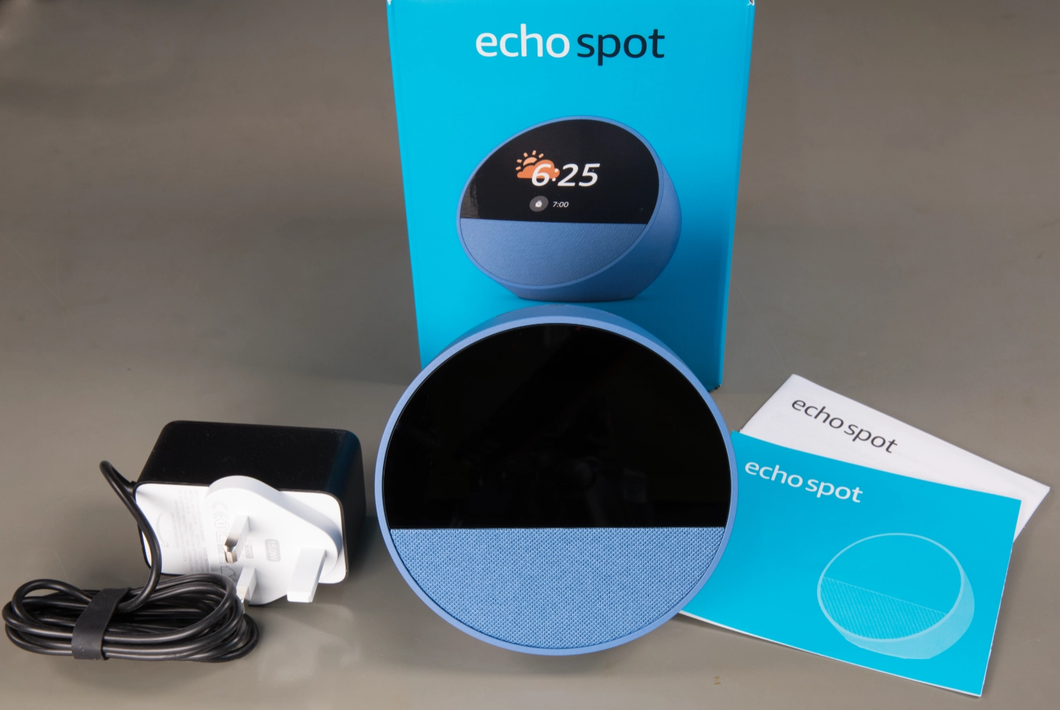
In this teardown, we will look at the new Amazon Echo Spot 2024, which is the latest Amazon Echo smart device and was sold from July 2024 in the UK. It currently costs £79.99 from Amazon UK. The device is advertised as a Smart alarm clock with vibrant sound + Alexa, with a flat front, a 2.83" screen at 240 x 320 resolution and a speaker below under a mesh cover.
We have previously torn down Amazon Echo devices, including the 3rd gen Dot, 3rd gen Dot with Clock, Echo Flex, Echo Input, Echo Dot 4th Generation, Echo 5th Generation and Echo Pop.
The new Echo Spot comes in three colours, Black, Glacier White and Ocean Blue.
The top has three buttons for Mic on/off, Volume Up and Volume Down.
The power input socket is on the rear of the device, and the base has a circular rubber pad to stop it from moving around on flat surfaces.
The device supports Wi-Fi, Bluetooth Low Energy Mesh, and Matter controller.
Specifications
- Size: 113 mm x 103 mm x 111 mm
- Weight: 405g
- Audio Speaker: 1.73 inch
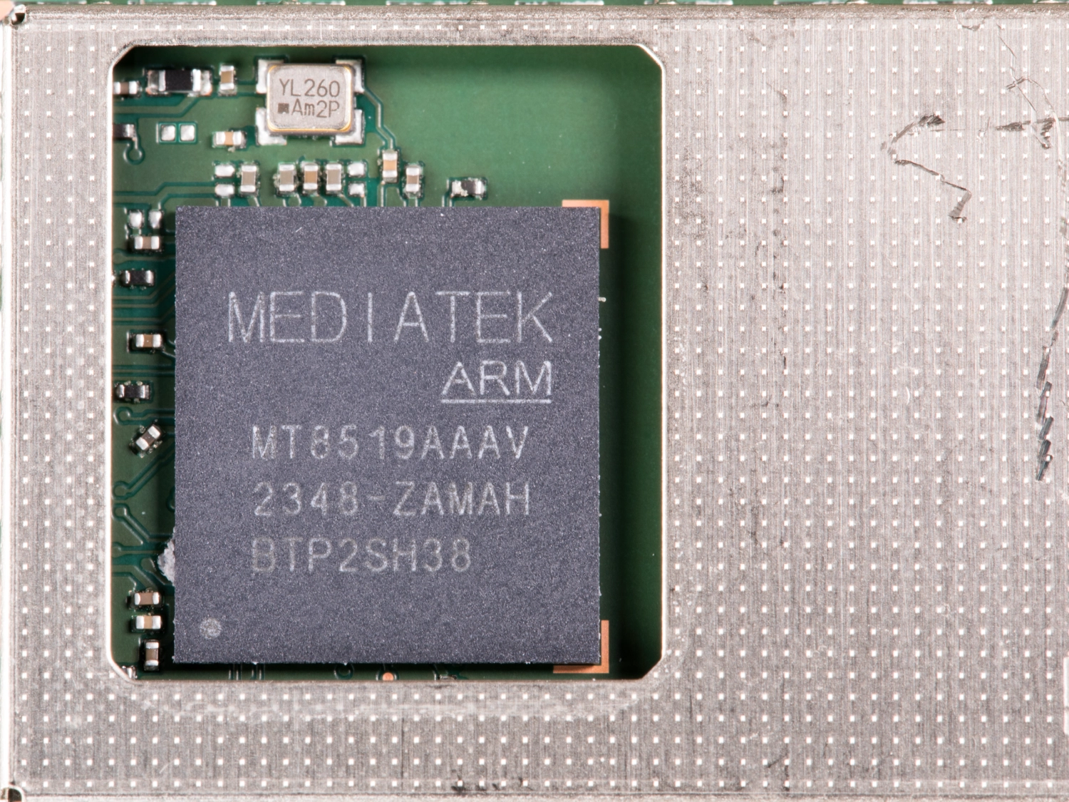
- Processor: MT8519
- Memory: 1 GB DRAM + 8 GB eMMC
In the Box
- The Echo Spot
- 240V UK power supply
- Setup instructions
- Terms of use
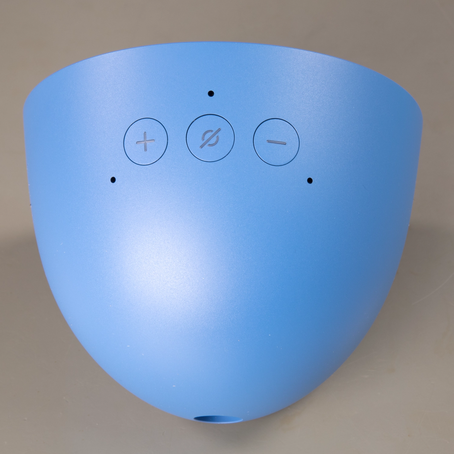
Top of the Echo Spot
The top of the smart speaker has three buttons. The + and – buttons control the volume, and a circle with a line through it which disables the microphones.
There are three small holes which are used by the internal microphones.
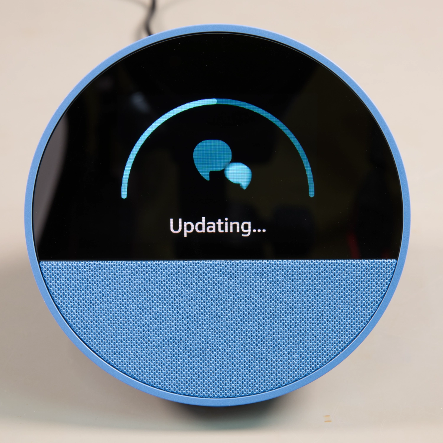
On the front edge of the case is a LED 2.83" screen with 240 x 320 resolution and a speaker below under a mesh cover.
Case Base
The base has the serial number, product logos, and certification marks.
On the rear is a power input socket. The Echo Spot does not have any external speaker inputs or outputs.
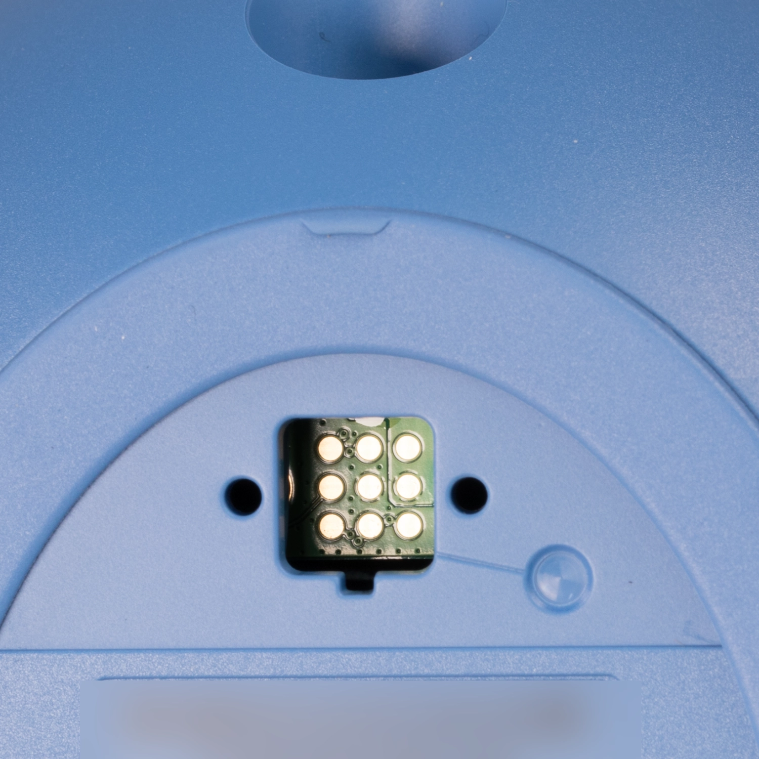
Removing a small sticker on the base revealed an access hole with PCB pads which supply power and USB data for programming the device.
Unlike some previous Amazon Echo devices we have torn down, the Echo Spot has no screws in the base, and access to the speaker and circuit boards is via the fabric-covered front panel.
All internal screws used a Torx T6 size driver apart from the speaker which used four J1 cross head screws.

Opening the Case
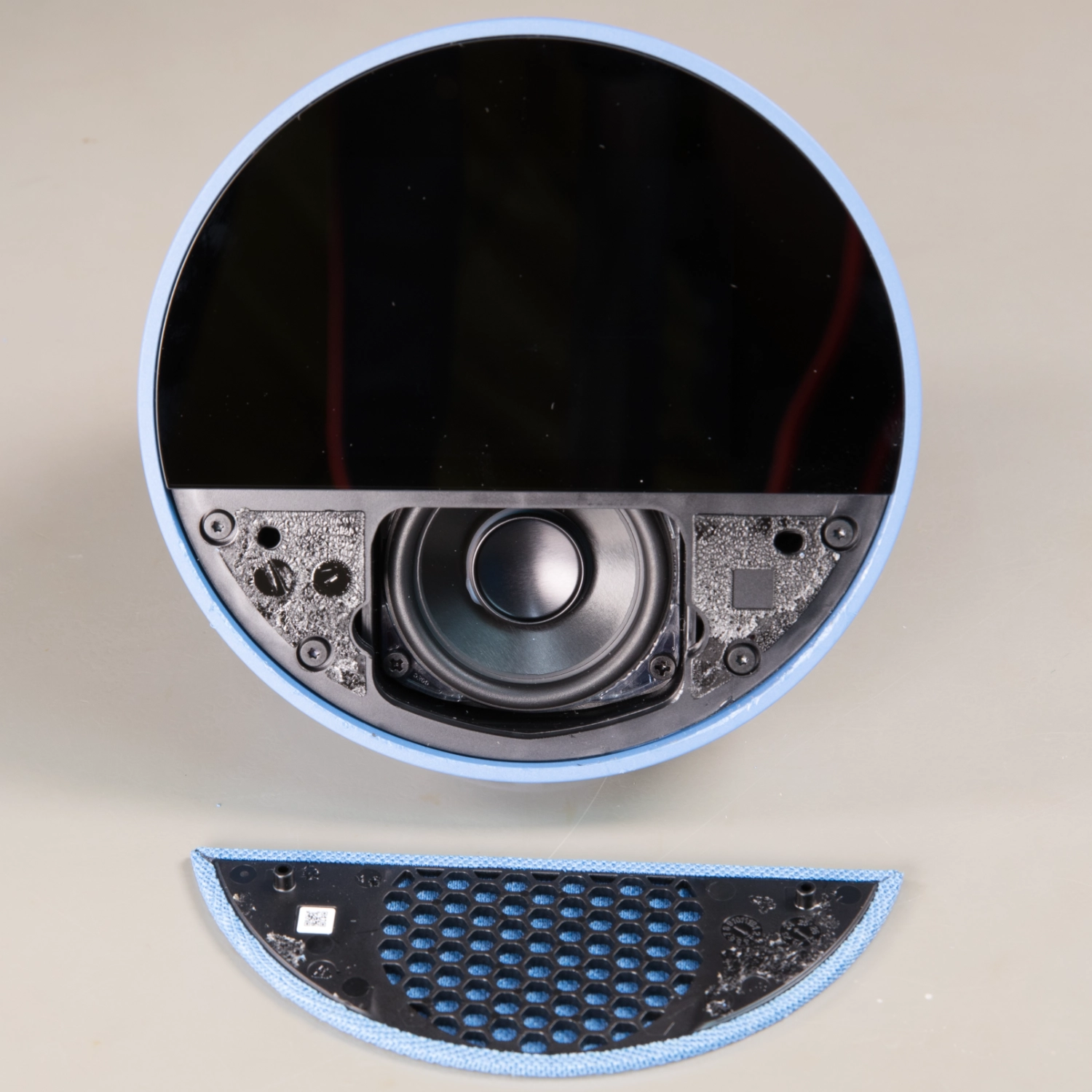
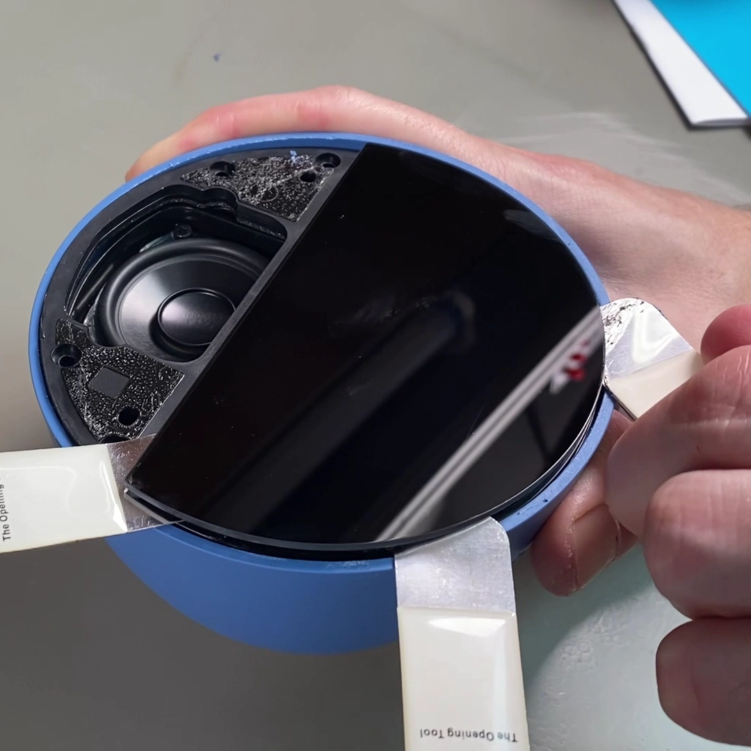
Accessing the inside of the device proved to be more challenging that some of the previous teardowns. The speaker cover grill is held in place with a strong adhesive requiring the use of metal spudger tools to carefully prise the fabric and plastic speaker cover away from the enclosure.
With the speaker cover removed, this revealed the speaker and T6 torx screws which secure the front plastic panel to the outer case with the curved glass panel and display mounted in the upper half.
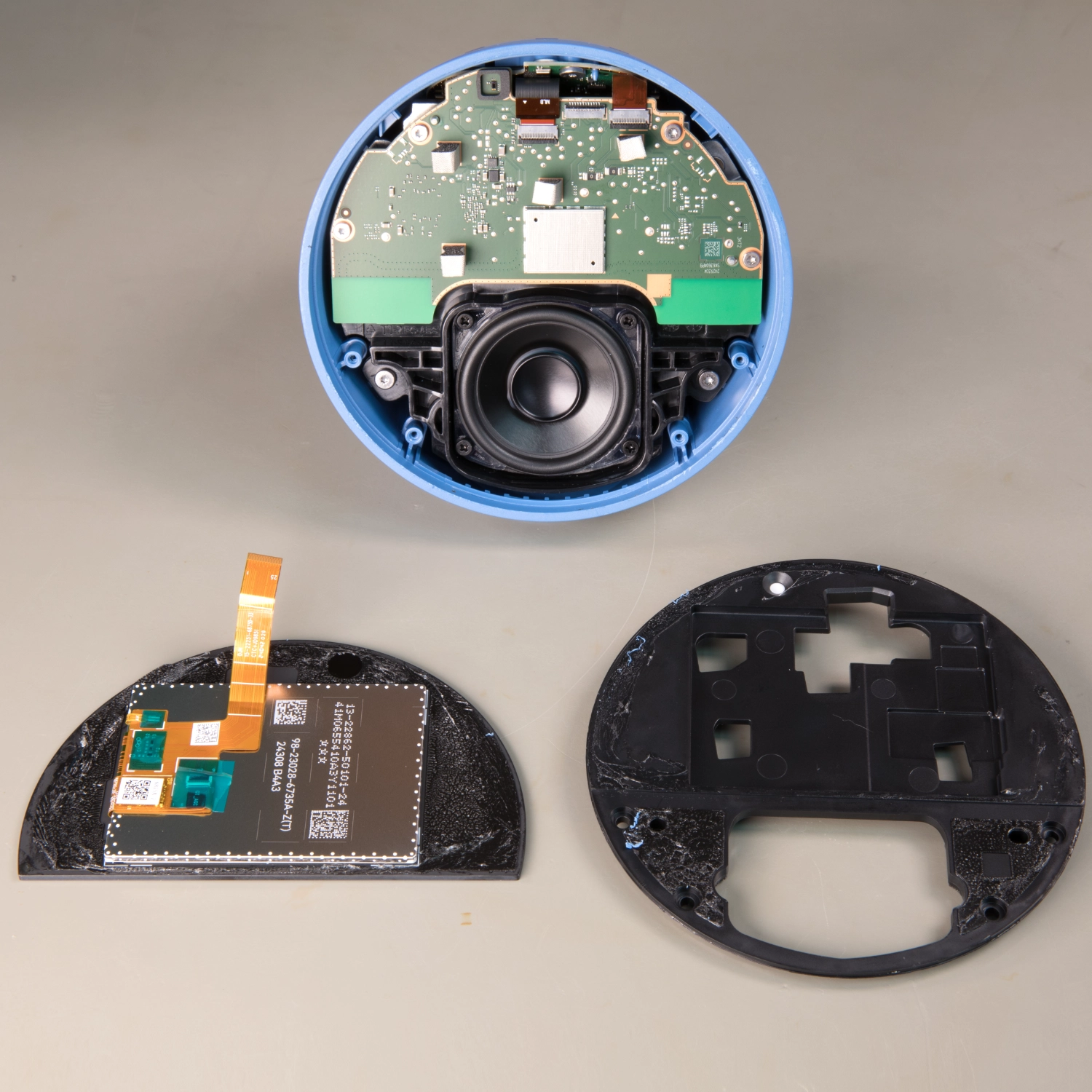
We removed the two outer screws and found that the plastic panel and display could not be removed and appeared to be fitted by more screws under the display which was later found to be rotating clips.
We used a hairdryer to gently heat the glass panel to soften the glue holding it in place and using the metal spludgers we carefully slid the tools between the glass and plastic to separate the display section from the plastic mount. Unfortunately whilst trying to remove the glass the LCD panel was damaged.
With the glass now removed this revealed that the front panel was held with two plastic clips which required the front panel to be rotated clockwise to remove and not screws as we previously thought.
A small flat flex cable connected the display module to the main circuit board.
Removing the main PCB
The large PCB containing the processor, memory, power supplies and audio amplifier is held in place with four T6 torx screws and has a flat flex cable connecting to the top PCB and a flat flex cable going to the power input PCB.
With the cables removed the PCB could be removed from the case.
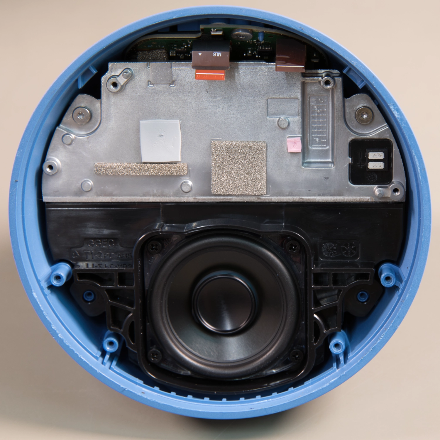
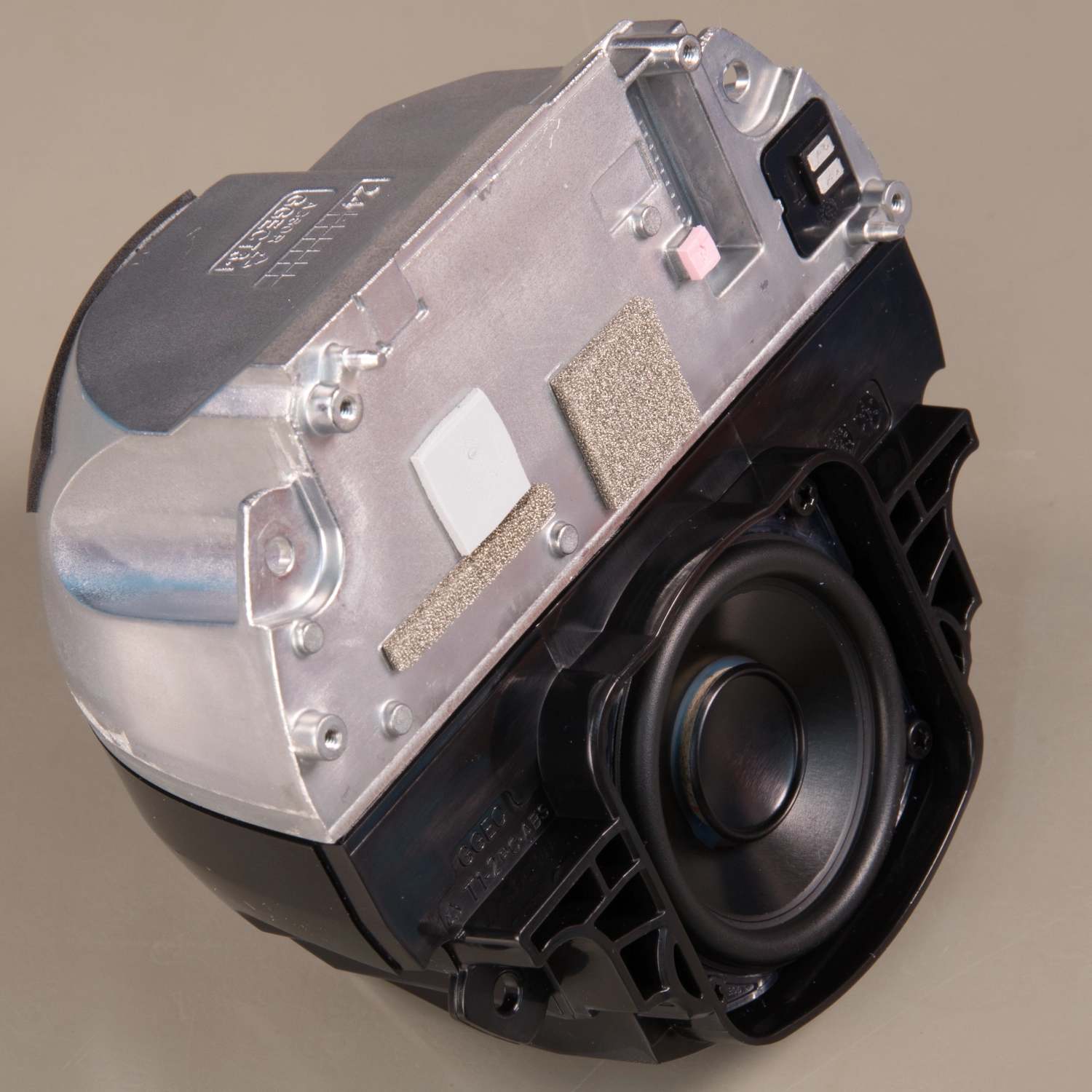
Speaker Enclosure
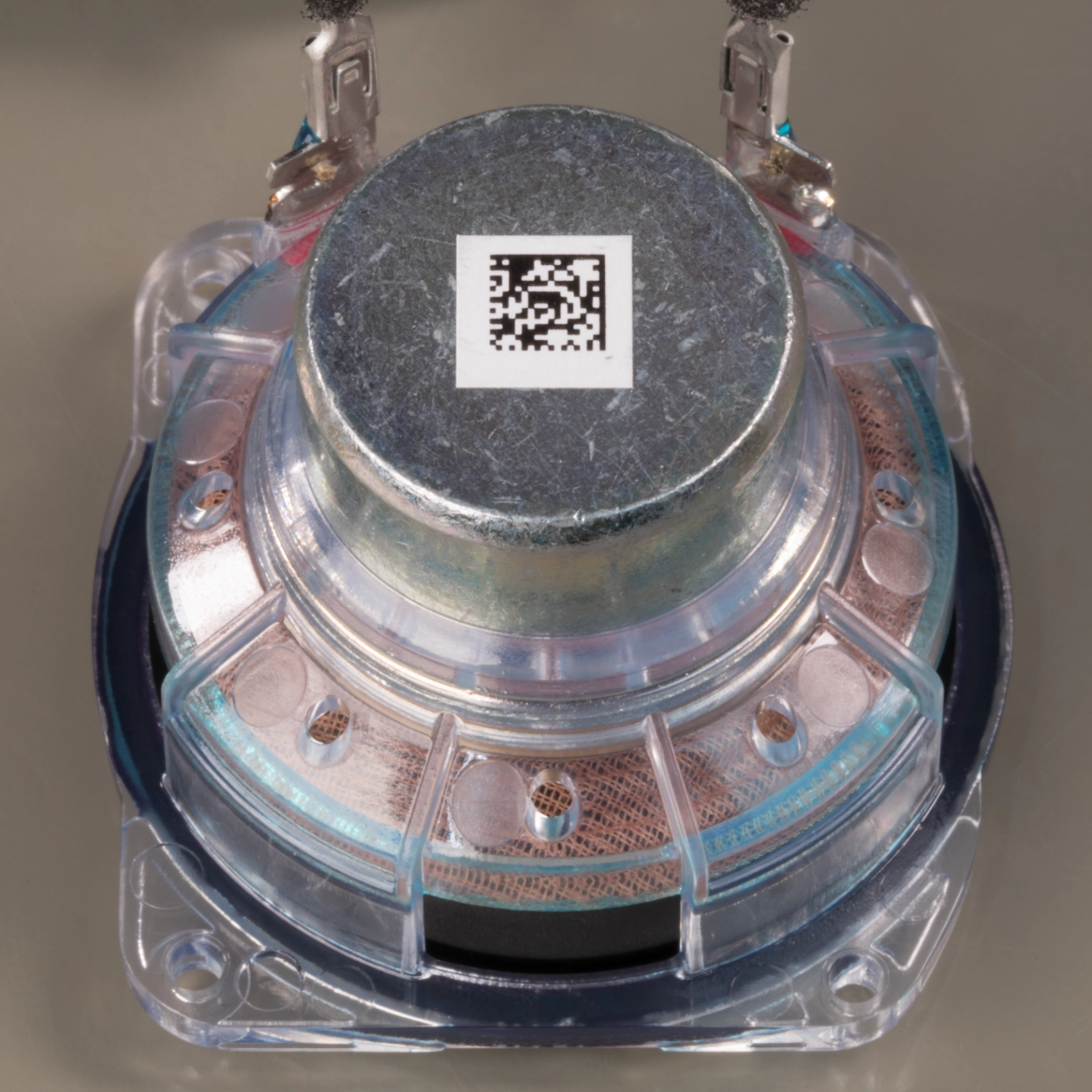
The single internal speaker measures 1.73 inches, 44mm and is inside a sealed black plastic enclosure with an aluminium heatsink around the sides to dissipate heat from the processor. This is held into the external case with two T6 torx screws.
The speaker is held in place with four J1 cross head screws
With these screws removed, the speaker can be removed from the plastic enclosure.
The speaker enclosure is connected to the PCB using small metal tabs that touch pads on the PCB to drive the speaker.
Audio, Button PCB and Power / Debug PCB
With the speaker enclosure removed, this provides access to a small power input PCB and the top PCB which contains the buttons and microphones.
The power input PCB is secured using two T6 torx screws, and the main PCB has three black T6 torx screws securing it to the main case. One of the screws is located under a small black rubber spacer.
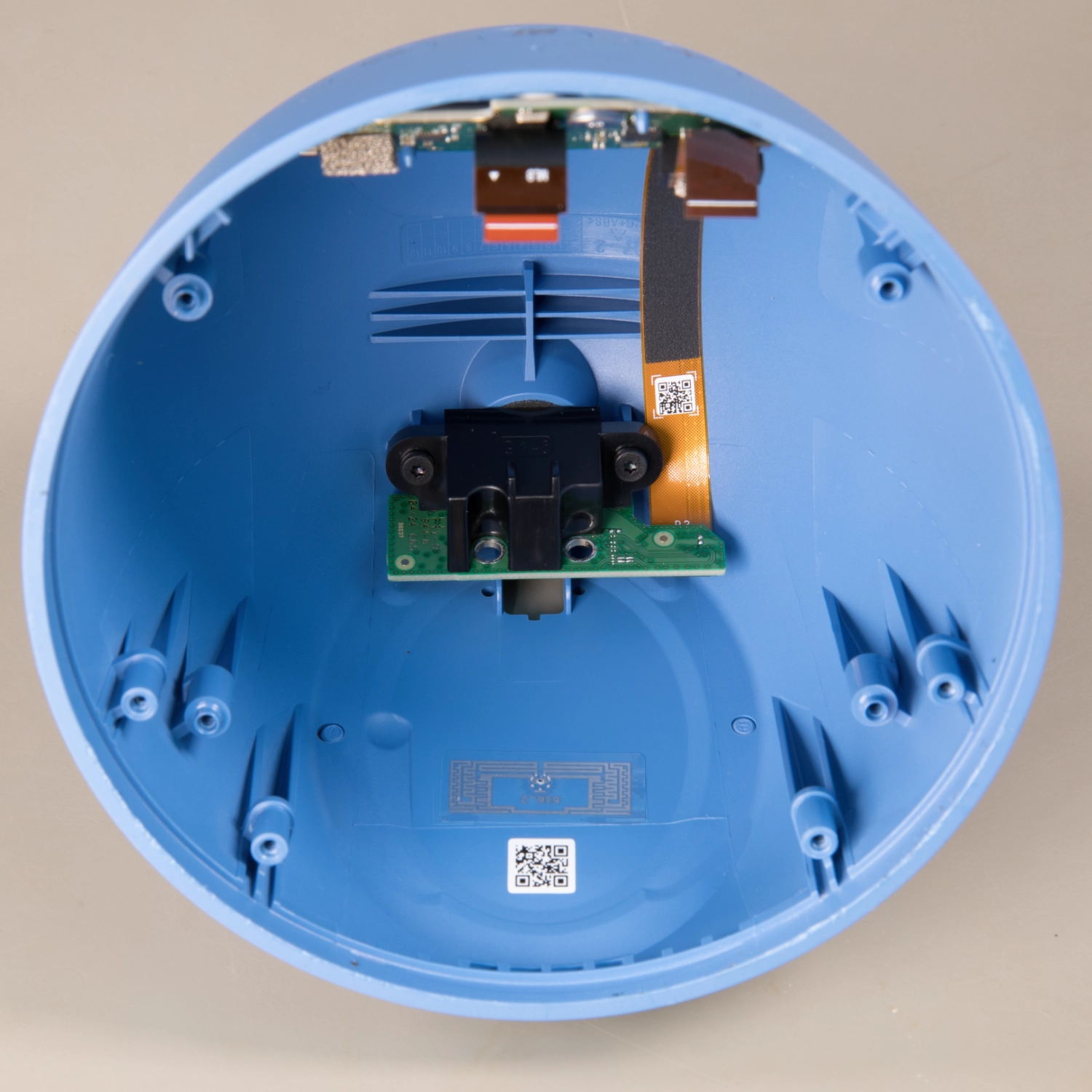
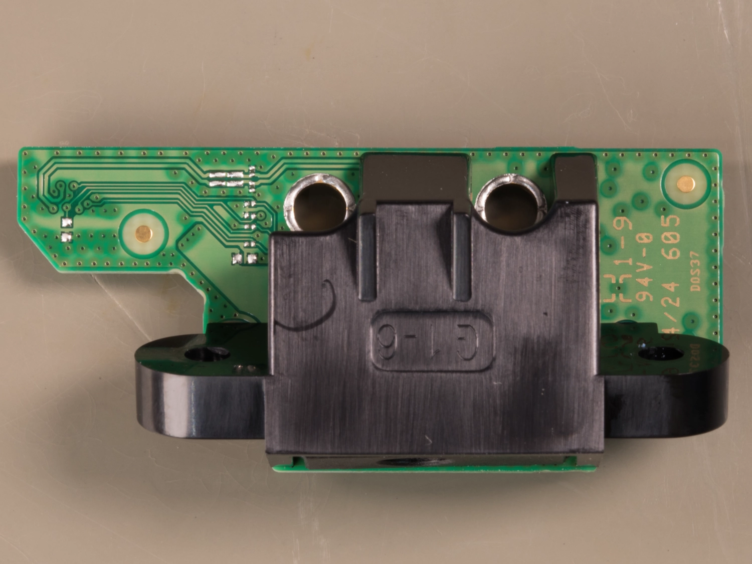
Power input and Debug header board
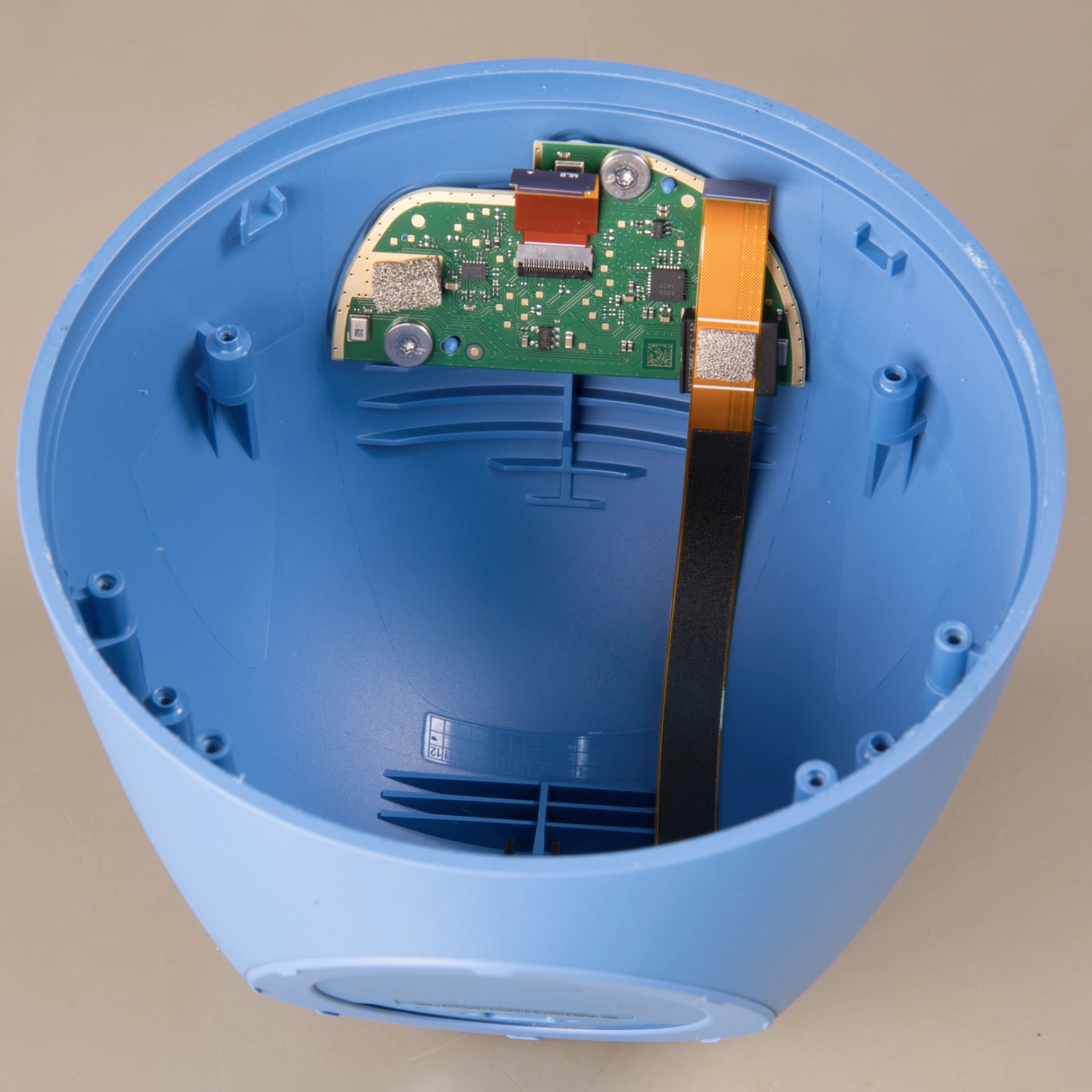
At the rear of the Echo Spot enclosure is a small power input PCB which connects to the processor PCB using a flat flex cable.
The upper side of this board contains the plastic mounting bracket and power input socket.
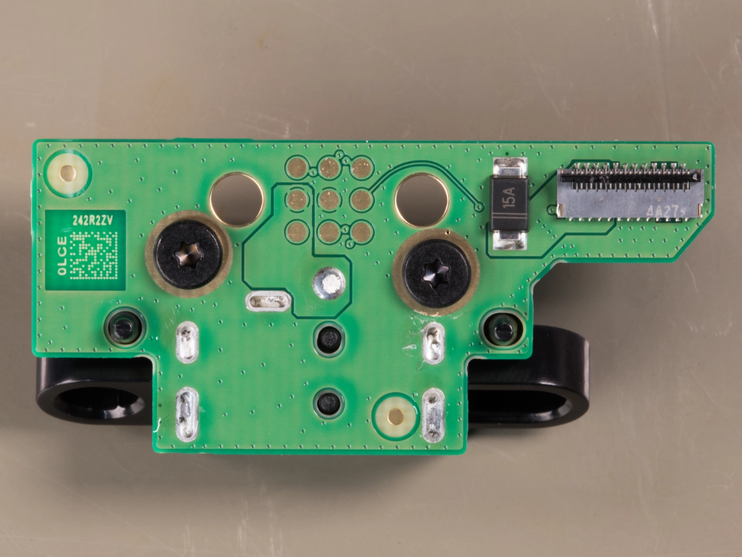
On the underside of this board is a grid of nine exposed pads with locator holes. These pads are visible when the Echo Spot is assembled under the base sticker. There is also a flat flex connector and reverse protection diode.
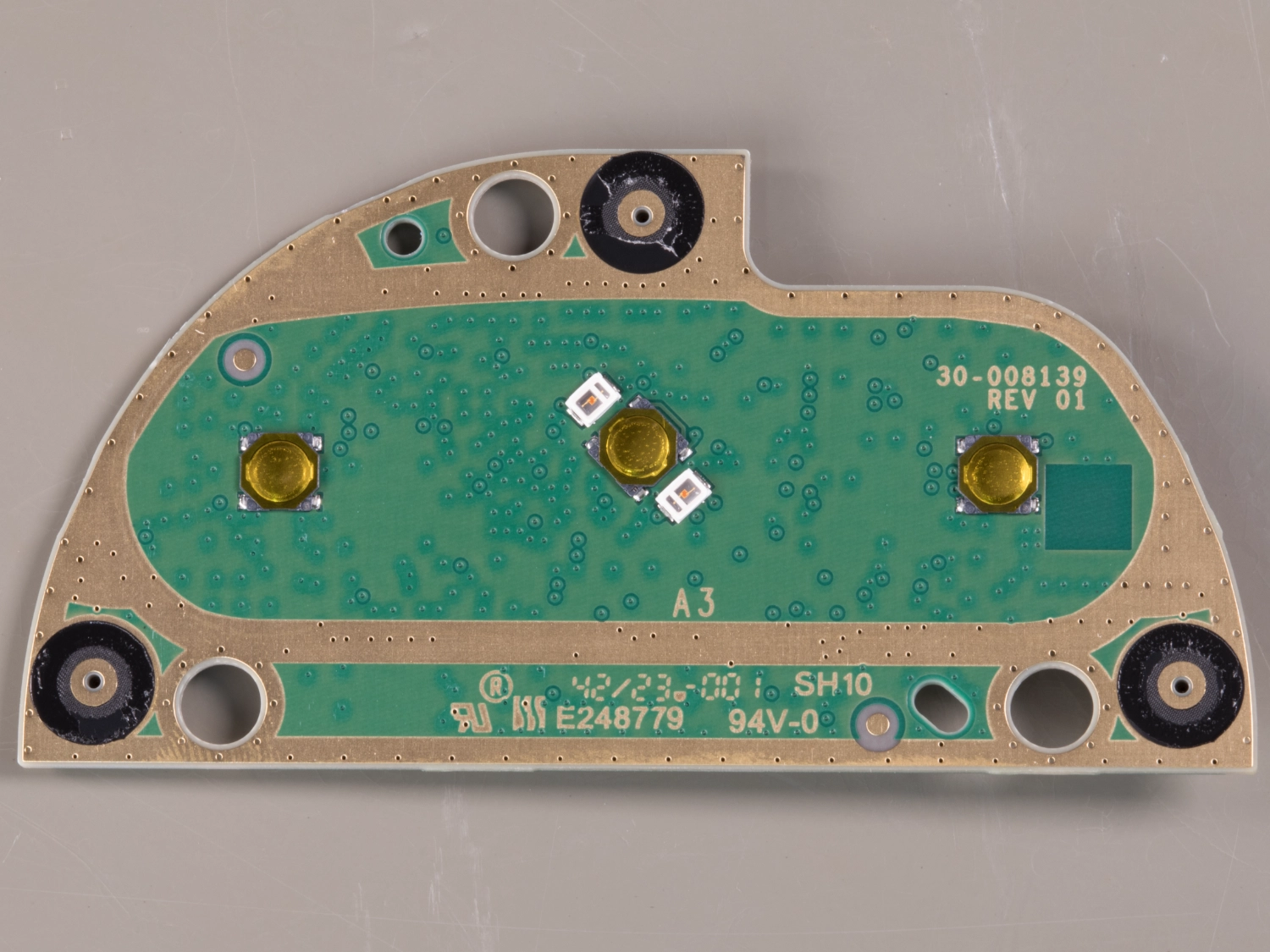
The upper side of the top PCB
This PCB marked SH10 mounts into the top of the case and contains:
Three surface mounted buttons.
Two LEDs next to the middle button.
Three black surrounded holes for the rear mounted microphones.
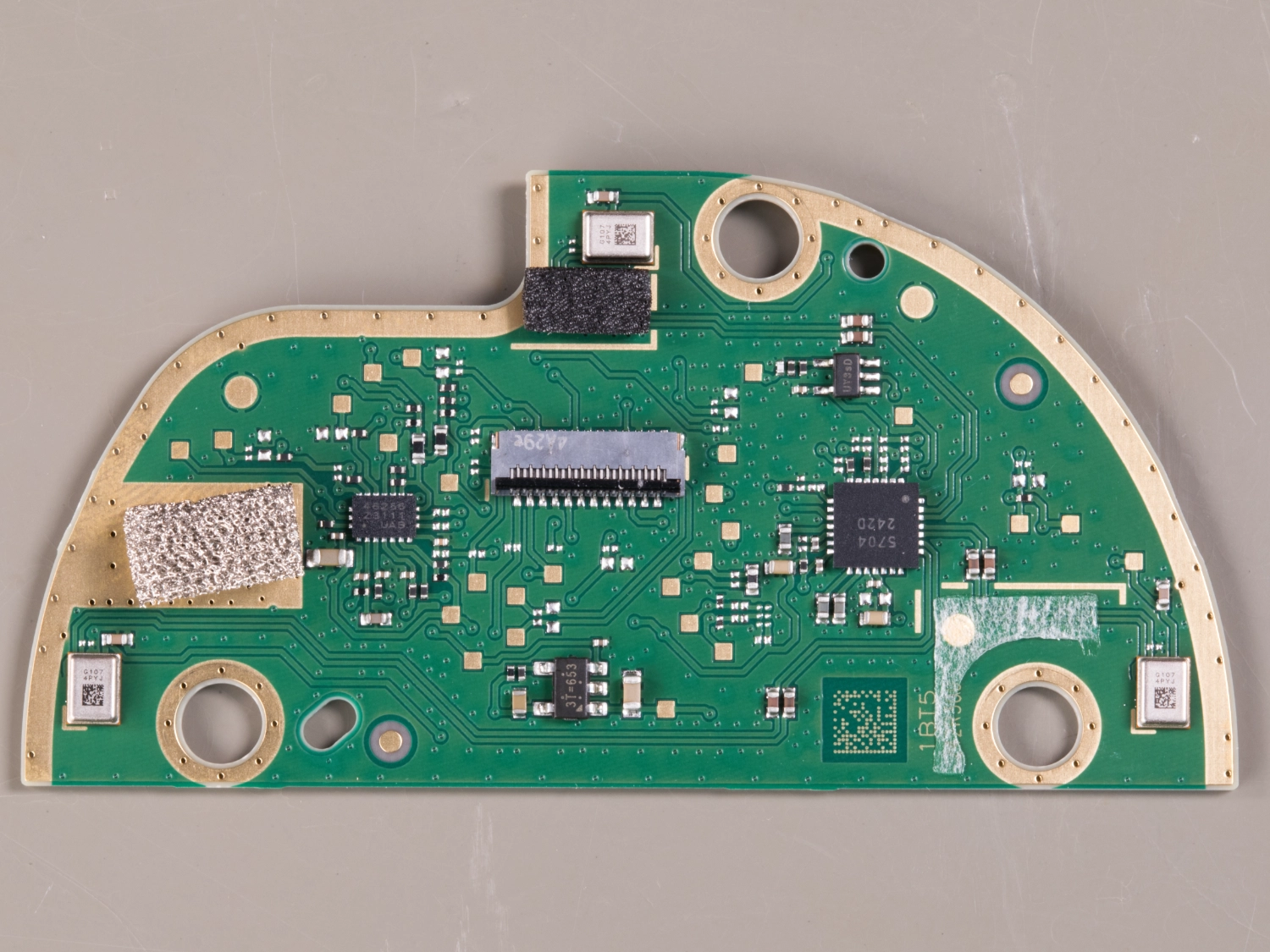
The lower side of the top PCB
This PCB marked SH10 mounts into the top of the case and contains:
Three surface mounted microphones, part number G1074PYJ.
ADC connected to the microphones, part number AK5704 from AsahiKASEI and is a 4-ch 32-bit ADC with MIC-Amp .
Controller chip, part number 46256 23111 UAB.
We have not been able to find more information for these components but based on what we found while probing the PCB with an oscillosope the chip marked 46256 appears to control the LEDs and mute functions.
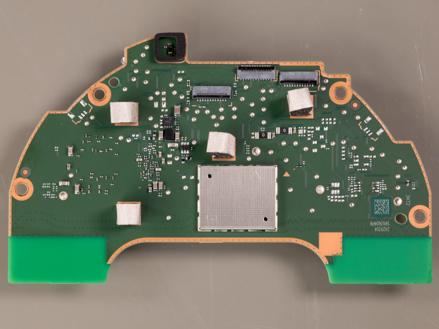
The upper side of the Processor PCB
On the upper edge of this PCB are three flat flex connectors which connect to the display, power and control boards.
There is a large shielded enclosure soldered to the board.
Below this cover is a SanDisk SDINBDG4-8G which is a eMMC 8GB flash drive with an eMMC 5.1 interface.
On the lower edge are PCB antennas for Wi-Fi and Bluetooth
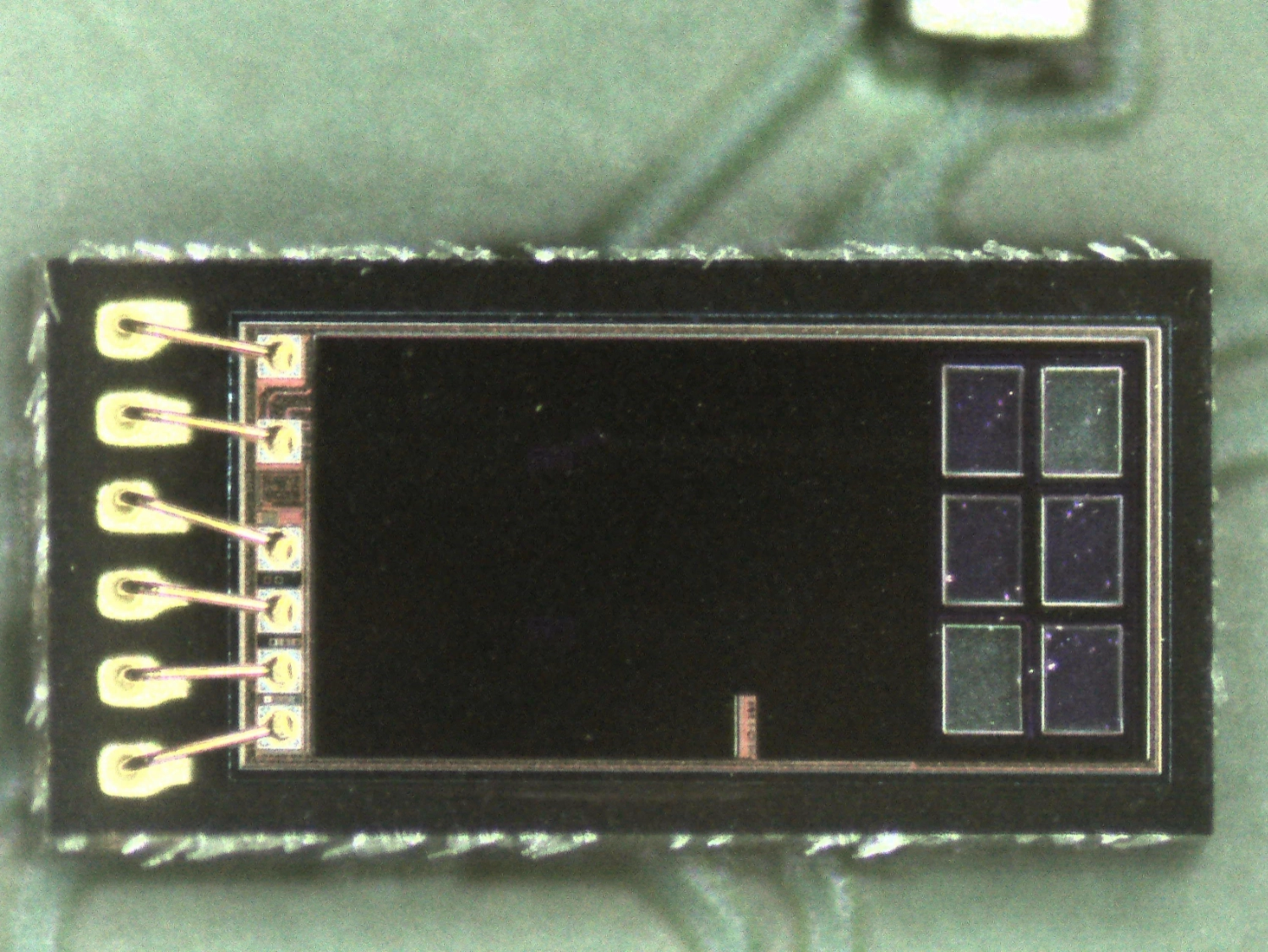
A light sensor is on the top edge of the board and this looks though a cutout in the glass front panel to control the dimming of the display depending on available light levels.
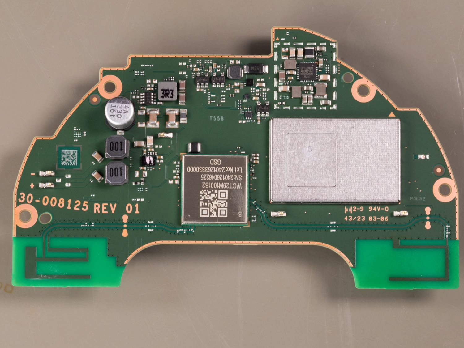
The lower side of the Processor PCB
The power regulation, processor, storage and Wi-Fi / Bluetooth are on the lower side of the main PCB.
The processor and ram are below a metal shielded cover which is clipped in place. Removing the cover reveals the processor which is a MediaTek Arm MT8519AAAV, this is a Arm Cortex-A35 with 4 cores running up to 1.3GHz. This is the same processor as used on the Echo Pop.
The cover has an additional shielded section which needs to be unsolded from the board. With this removed you can access the Skhynix 8Gb DDR4 memory ID, part number H54G36AYRB.
The Wi-Fi and Bluetooth module part number WCT29M1001B2 and is based on MediaTek MT7653BSN chipset which features a low power 1x1 11a/b/g/n/ac dual-band Wi-Fi and a Bluetooth. The Wi-Fi subsystem contains the 802.11a/b/g/n/ac radio. It has a 32-bit RISC MCU that handles Wi-Fi and Bluetooth tasks. The Bluetooth subsystem contains the Bluetooth radio, baseband, link controller. It also uses the 32-bit RISC MCU for the Bluetooth protocols.
Power regulation is provided by chips marked 02=691 and 3T=653.
Audio for the speaker is provided by a Analog Devices MAX98396 Digital Input Class-DG Amplifier with I/V Sense and Brownout Prevention. This IC had a pink heatsink compound on the top where it connects to the heatsink.
On the lower edge are PCB antennas for Wi-Fi and Bluetooth
Connecting USB to the computer
We used a spare USB cable to solder connections to the GND, D+ and D- pins and after connecting this to the computer, we entered the bootloader mode by holding the volume down button and mute button, then connecting the power.
After a few seconds, the display shows "Fastboot" but we were not able to get a USB connection to the computer. The USB maybe disabled once the operating system has been installed or one of the other pins on the debug header may need to be pulled high or low to enable the USB port.
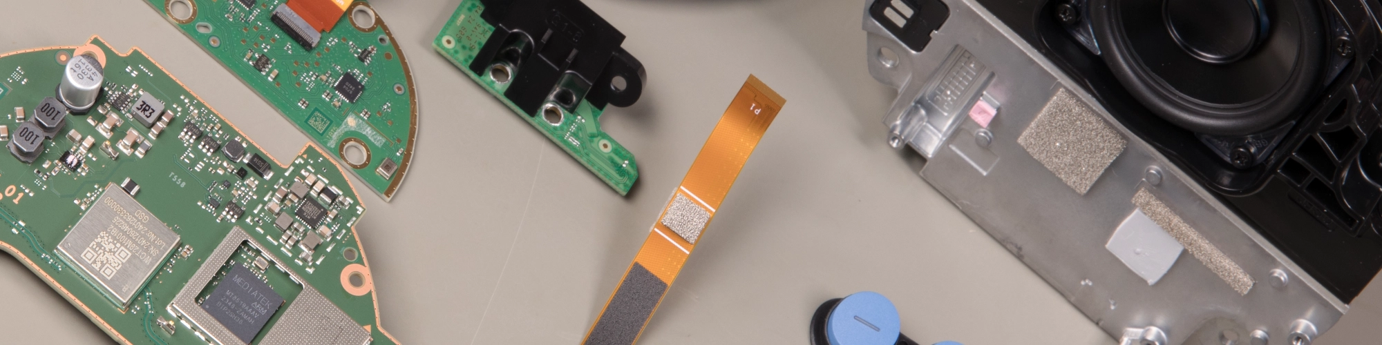
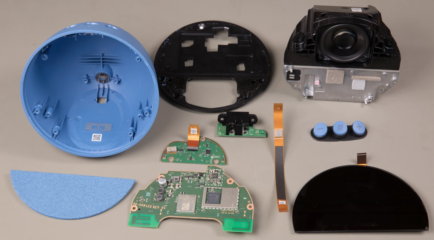
All internal parts
All the internal parts that make up the Echo Spot.
Power Consumption
We measured the peak power consumption of the Amazon Echo Spot with a Hopi mains power meter.
| Device Status | Power in Watts |
|---|---|
| Idle waiting for input | 1.5W |
| Responding to a user command | 1.8W |
| Medium volume with music playing | 1.8W |
| Maximum volume with music playing | 3.2W |
Probing the test points
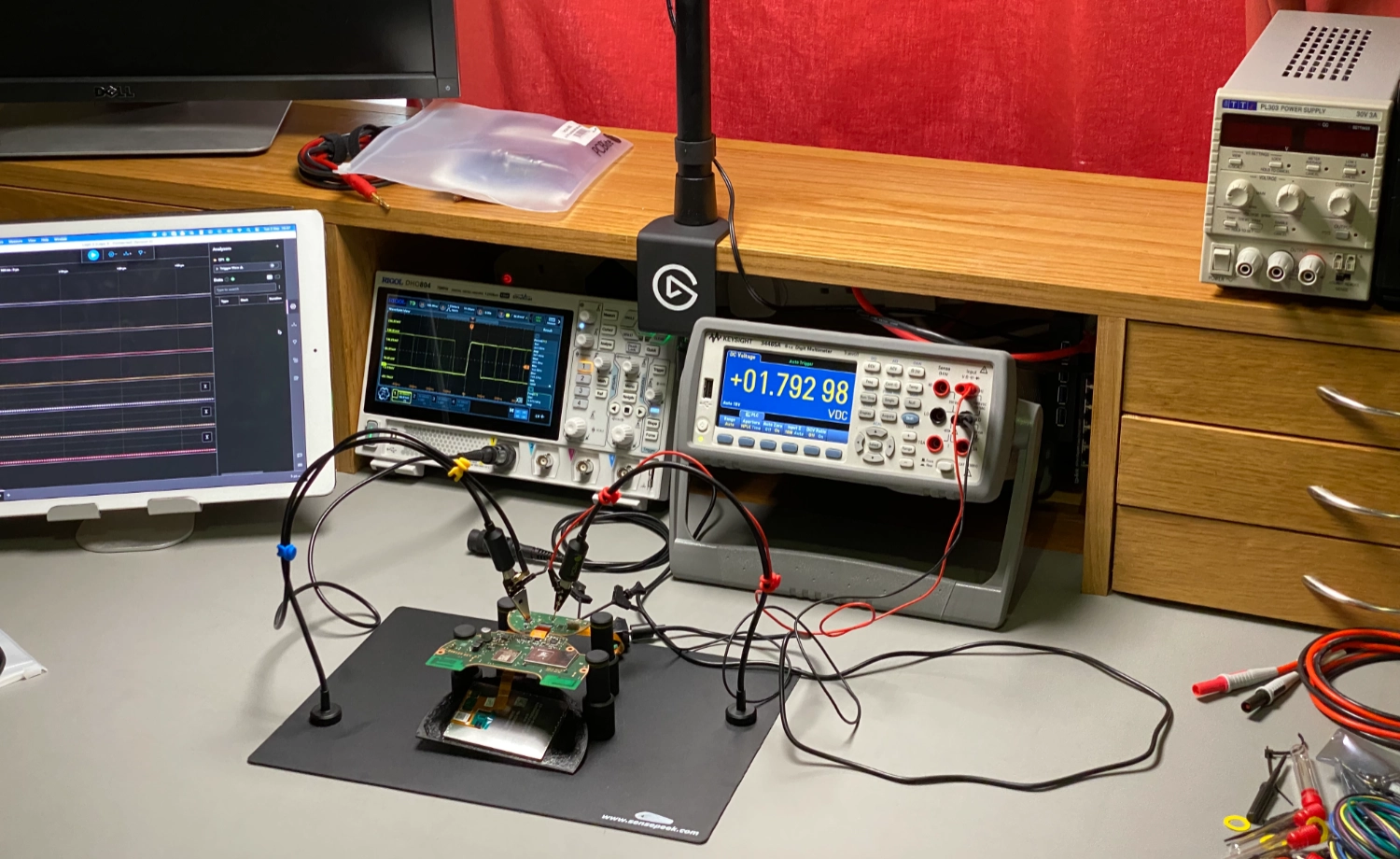
We have setup a new electronics development bench to enable us to work on projects which require a computer and we added our Keysight 34465A 6.5 Digit Multimeter and new Rigol DHO804 4CH, 12Bit, 70MHz, 1.25GSa/s USB Powered Digital Oscilloscope and other assorted test equipment.
To enable us to securely hold circuit boards and test probes in place we purchased a PCBite kit with 2X 200MHz and 4X SP10 handsfree probes which has a metal base and magnets in the probe holders so they can be moved to hold the spring loaded probes on test points on the PCB being tested.
The new workbench allows us to have test equipment and projects setup for longer periods unlike our loft workshop where we often have to clear the bench to enable us to build the Raspberry Pi development boards.
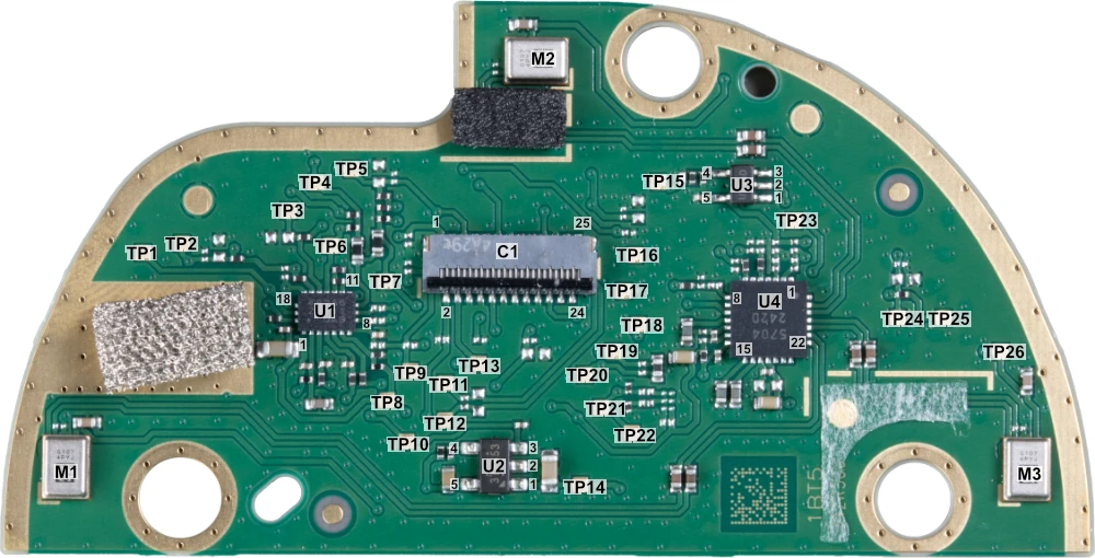
Microphone and Switch PCB
The microphone and switch PCB contains 26 test points. After checking with a multimeter and oscilloscope, we were able to determine the purpose of many of the test points as shown on the following table.
| Test Point | Voltage | Connects to | Notes |
|---|---|---|---|
| TP1 | 0V | ||
| TP2 | 1.8V | Volume Up | |
| TP3 | 1.8V | ||
| TP4 | 3.7V | 1.8V when mute pressed | |
| TP5 | 3.8V | Mute Switch | |
| TP6 | 785mV | ||
| TP7 | 1.8V | ||
| TP8 | 3.8V | ||
| TP9 | 1.8V | Square Wave at 1.562khz | |
| TP10 | 3.8V | Goes to 0V when muted and 3.8V when microphone enabled | |
| TP11 | 0V | ||
| TP12 | 0V | ||
| TP13 | 1.8V | Goes low on any button press, interupt trigger | |
| TP14 | 3.3V | ||
| TP15 | 0V | ||
| TP16 | 1.8V | Sine Wave 24.6Mhz | |
| TP17 | 1.8V | Square Wave 12.3Mhz | |
| TP18 | 1.8V | Square Wave 96khz | |
| TP19 | 0V | ||
| TP20 | 0.9V | ||
| TP21 | 1.8V | ADC I2C SDA | |
| TP22 | 1.8V | ADC I2C SCL | |
| TP23 | 1.8V | ADC PDM | |
| TP24 | 1.8V | Volume Down | |
| TP25 | 1.8V | ADC TVD | |
| TP26 | 3.3V | Microphone power, goes to 0V when muted |
Components
| Reference | Marking | Type | Manufacturer |
|---|---|---|---|
| C1 | 4A29e | 25 Pin FPC/FFC connector | Unknown |
| M1 | G107 4PYJ | Microphone | Unknown |
| M2 | G107 4PYJ | Microphone | Unknown |
| M3 | G107 4PYJ | Microphone | Unknown |
| U1 | 46256 Z3111 UAB | Unknown | Unknown |
| U2 | 3T=653 | Linear Voltage Regulator | Unknown |
| U3 | UY3sD | Linear Voltage Regulator | Unknown |
| U4 | 5704 242D | Low-Power 4-ch 32-bit ADC with MIC-Amp | Asahi Kasei Microdevices Corporation AK5704 |
Power Input and Debug PCB
The power input and debug PCB contains 9 test points. After checking with a multimeter and oscilloscope, we were able to determine the purpose of many of the test points as shown on the following table.

Notes
Power input voltage: 12.2V DC
Test Points
| Test Point | Voltage | Connects to | Notes |
|---|---|---|---|
| TP1 | 6.3mV | C2 - Pin 20 | |
| TP2 | 11.2mV | C2 - Pin 23 | USB |
| TP3 | 11.2mV | C2 - Pin 22 | USB |
| TP4 | 12.2V | Input Connector Centre Pin | Power Input |
| TP5 | GND | Input Connector Outer Pin | Power GND |
| TP6 | 0V | C2 - Pin 21 | |
| TP7 | 0V | Not Used | |
| TP8 | 1.8V | C2 - Pin 19 | |
| TP9 | 1.8V | C2 - Pin 18 |
Components
| Reference | Marking | Type | Manufacturer |
|---|---|---|---|
| C2 | 4A27s | 25 Pin FPC/FFC connector | Unknown |
Connections
| Pin | |
|---|---|
| 1 | 12V |
| 2 | 12V |
| 3 | 12V |
| 4 | 12V |
| 5 | 12V |
| 6 | 12V |
| 7 | 12V |
| 8 | 12V |
| 9 | 12V |
| 10 | NC |
| 11 | GND |
| 12 | GND |
| 13 | GND |
| 14 | GND |
| 15 | GND |
| 16 | GND |
| 17 | GND |
| 18 | TP9 |
| 19 | TP8 |
| 20 | TP1 |
| 21 | TP6 |
| 22 | TP3 |
| 23 | TP2 |
| 24 | GND |
| 25 | GND |
Main Board
The main PCB contains 69 test points. After checking with a multimeter and oscilloscope, we were able to determine the purpose of many of the test points as shown on the following table.
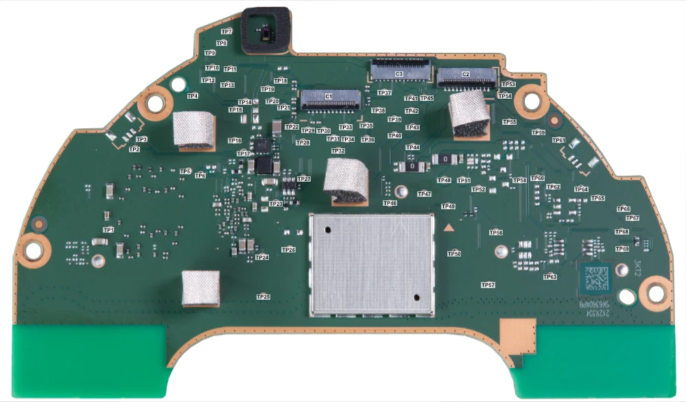
| Test Point | Voltage | Connects to | Notes |
|---|---|---|---|
| TP1 | 1.1V | ||
| TP2 | 0V | ||
| TP3 | 1.8V | ||
| TP4 | 865mV | ||
| TP5 | 0V | ||
| TP6 | 900mV | ||
| TP7 | 3.8V | ||
| TP8 | 1.8V | ||
| TP9 | 3.8V | ||
| TP10 | 3.8V | ||
| TP11 | 1.8V | ||
| TP12 | 1.8V | Data | |
| TP13 | 1.8V | Clock 1Mhz | |
| TP14 | 0V | ||
| TP15 | 3.3V | ||
| TP16 | 0V | ||
| TP17 | 900mV | ||
| TP18 | 3.8V | ||
| TP19 | 1.1V | ||
| TP20 | 1.8V | Square Wave 1.56kHz | |
| TP21 | 1.8V | ||
| TP22 | 1.8V | ||
| TP23 | 800mV | ||
| TP24 | 800mV | ||
| TP25 | 1.8V | ||
| TP26 | 0V | ||
| TP27 | 687mV | ||
| TP28 | 1.8V | ||
| TP29 | 1.8V | ||
| TP30 | 1.8V | ||
| TP31 | 1.8V | Sine Wave 24.6Mhz | |
| TP32 | 1.8V | Square Wave 12.3Mhz | |
| TP33 | 1.8V | Square Wave 96Khz | |
| TP34 | 1.8V | Audio Data | |
| TP35 | 0V | ||
| TP36 | 880mV | ||
| TP37 | 1.8V | ||
| TP38 | 3.3V | ||
| TP39 | 12V | ||
| TP40 | 1.8V | ||
| TP41 | 23V | ||
| TP42 | 0V | ||
| TP43 | 12V | ||
| TP44 | 12V | ||
| TP45 | 3.3V | ||
| TP46 | 0V | ||
| TP47 | 1.8V | ||
| TP48 | 12V | ||
| TP49 | 1.8V | ||
| TP50 | 800mV | ||
| TP51 | 12V | ||
| TP52 | 1.8V | ||
| TP53 | 0V | ||
| TP54 | 0V | ||
| TP55 | 0V | ||
| TP56 | 1.8V | ||
| TP57 | 0V | ||
| TP58 | 0V | ||
| TP59 | 12V | ||
| TP60 | 0V | ||
| TP61 | 1.8V | ||
| TP62 | 0V | ||
| TP63 | 0V | ||
| TP64 | 0V | ||
| TP65 | 1.8V | ||
| TP66 | 1.8V | ||
| TP67 | 1.8V | ||
| TP68 | 0V | ||
| TP69 | 0V |
High Resolution Images
I have a gallery of higher resolution images from this teardown on a Flickr album.


Boris
The MediaTek MT8519 is not the same as MT8516. Even back in 2018, the first Echo Spot used ARM with 4x A53 (not 35) cores. The MT8516 I think it's custom SoC made for Amazon featuring their AI stuff dubbed "Amazon AZ2"
That was 1st gen AZ1 (Echo Dot 4th generation) - https://www.mediatek.com/blog/amazon-az1-neural-edge-processor-powered-by-mediatek
It was MT8512. And as you can see it was using 2GHz dual-core.