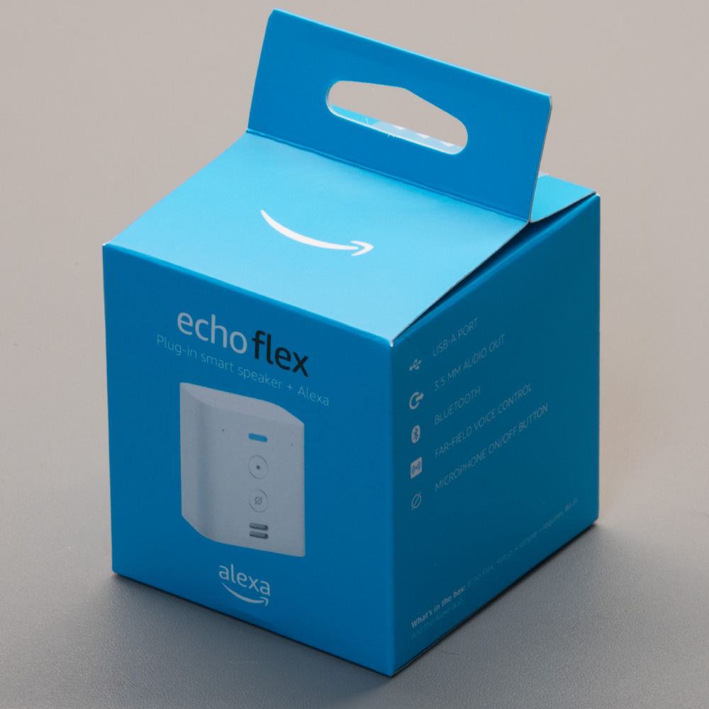
At Christmas, we purchased an Amazon Echo Flex which was on special offer at the time. The Echo Flex is a plug-in smart home controller using the Amazon Alexa ecosystem. After having it sitting on the shelf for 3 months, we finally took it apart to see what was inside.
The Echo Flex has two microphones, a small speaker, Audio Output via a 3.5mm jack and a USB type A port for charging devices and adding expansion devices. The Flex is controlled by voice commands to compatible smart home devices.
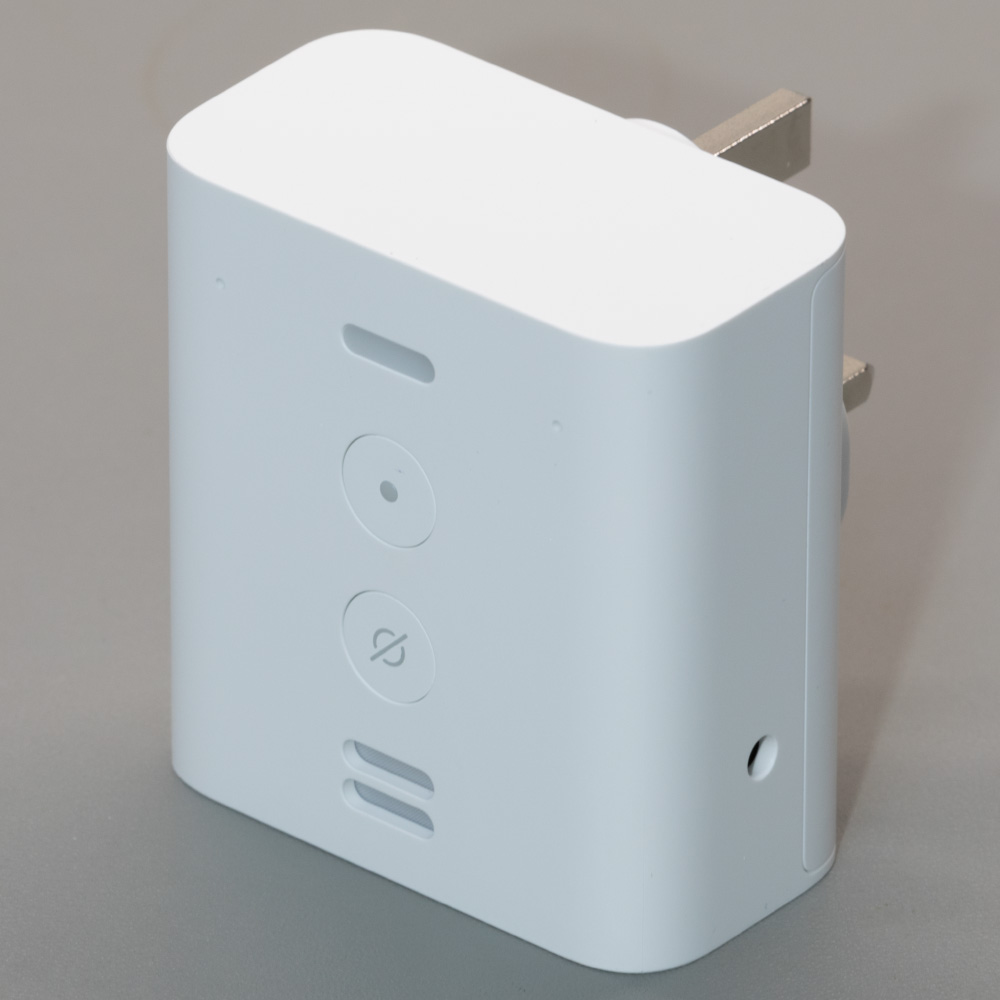
Front of the Echo Flex
The front of the Echo Flex has an indicator LED, two microphone holes, an Action button, Mic On/Off button and a mini speaker and measures 67mm x 72mm
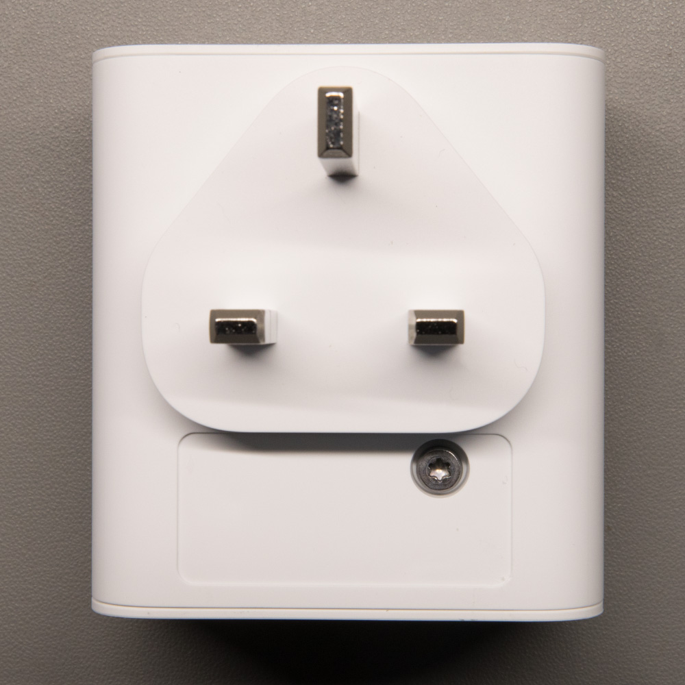
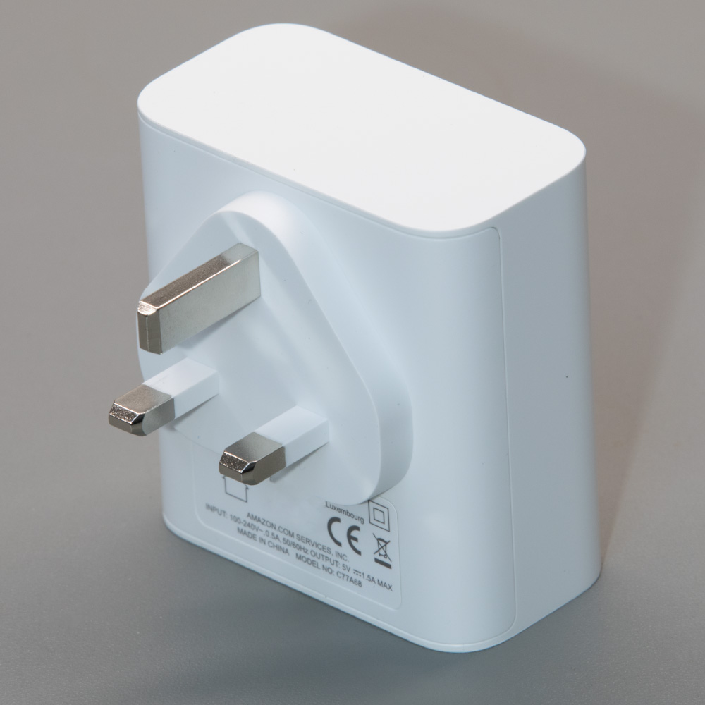
Back of the Echo Flex
The back has a UK mains power plug and model information sticker with serial number, product logos and certification marks.
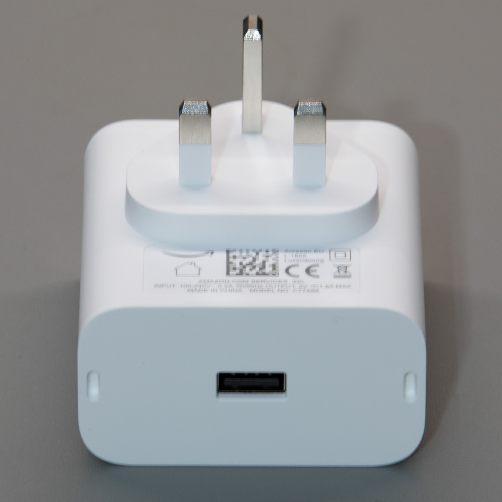
The base of the Echo Flex
The base has a single USB Type-A port which can supply up to 7.5W of power and two locator holes for accessories.
Side of the Echo Flex
One side of the Flex is plain plastic and the other side has a single hole for the 3.5mm stereo audio output.
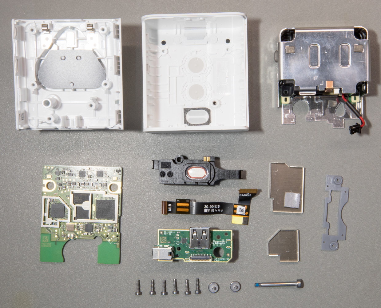
Opening the Case
As this is a mains electric powered device with a built-in power supply, only take it apart at your own risk. I am not responsible if you electrocute yourself, set your house on fire or some other disaster!
To remove the plastic cover, first, remove the sticker below the power input pins which will reveal a Torx screw.
Removing this screw and sliding a thin piece of metal between the two halves to release the plastic clips will allow you to separate the two parts of the case revealing the two circuit boards which are connected via a small flat-flex cable.
Internal and PCBs
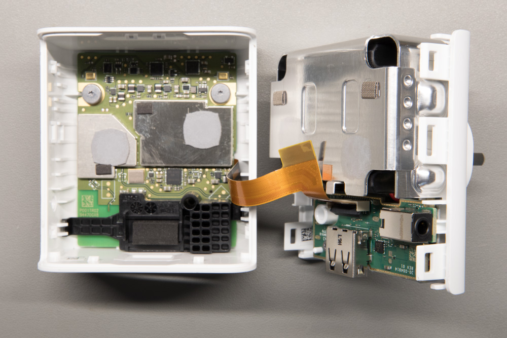
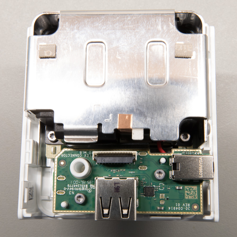
Power Supply
The power supply is a switching PSU with a 240V AC input and a 5V DC output. It is a completely sealed unit with a plastic enclosure wrapped in an aluminium shield.
We tried to remove the metal shield to get to the internals but it is designed in such a way that it would be difficult to disassemble and then reassemble into the same shape without the original metal folding tools so we left the PSU alone.
USB Board
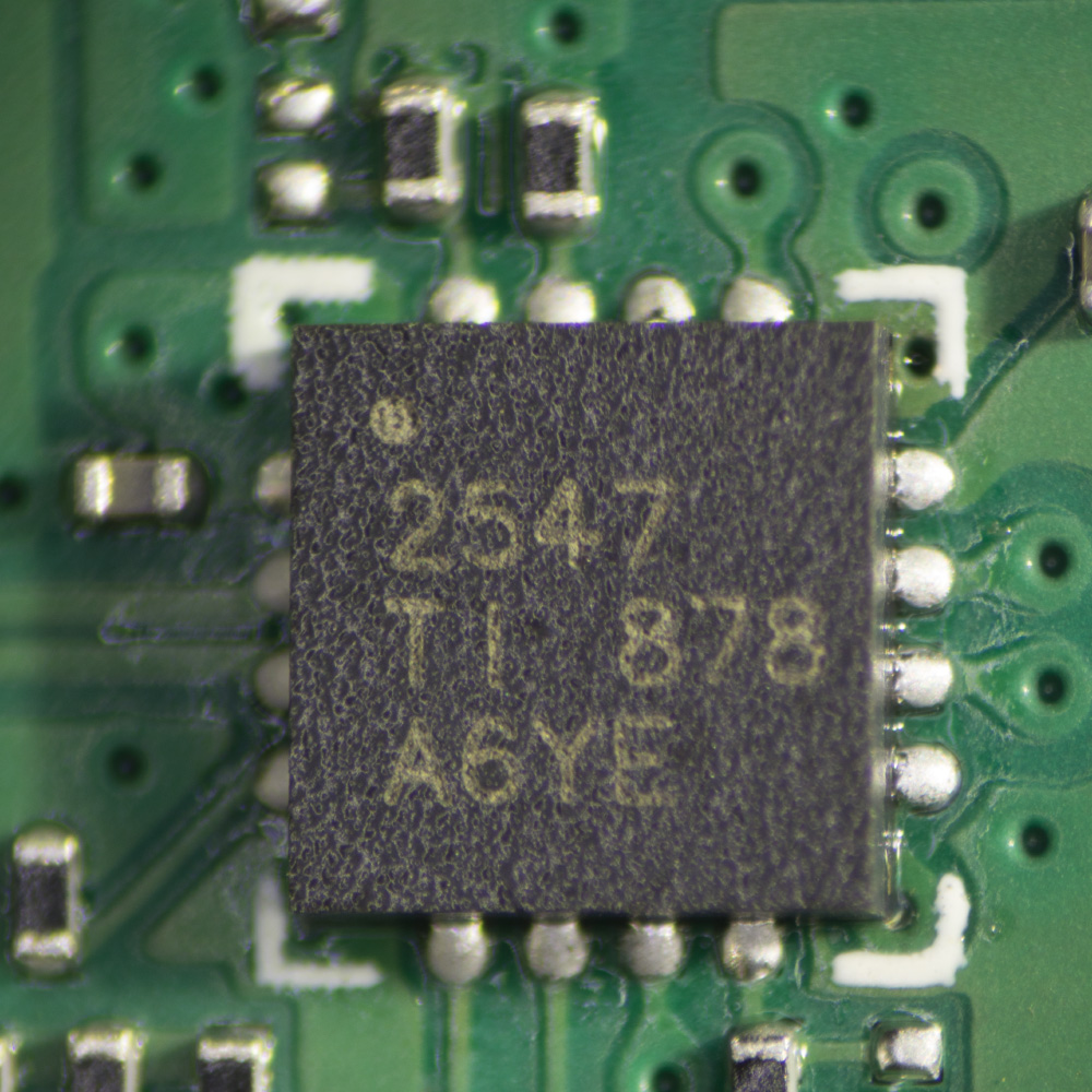
Next to the PSU is a small PCB containing the USB socket, 3.5mm audio jack socket and a flat flex connector. The only components on the board are a TPS2547 USB charging port controller from Texas Instruments and a few discreet resistors and capacitors.
The board is secured to the case with two Torx screws.
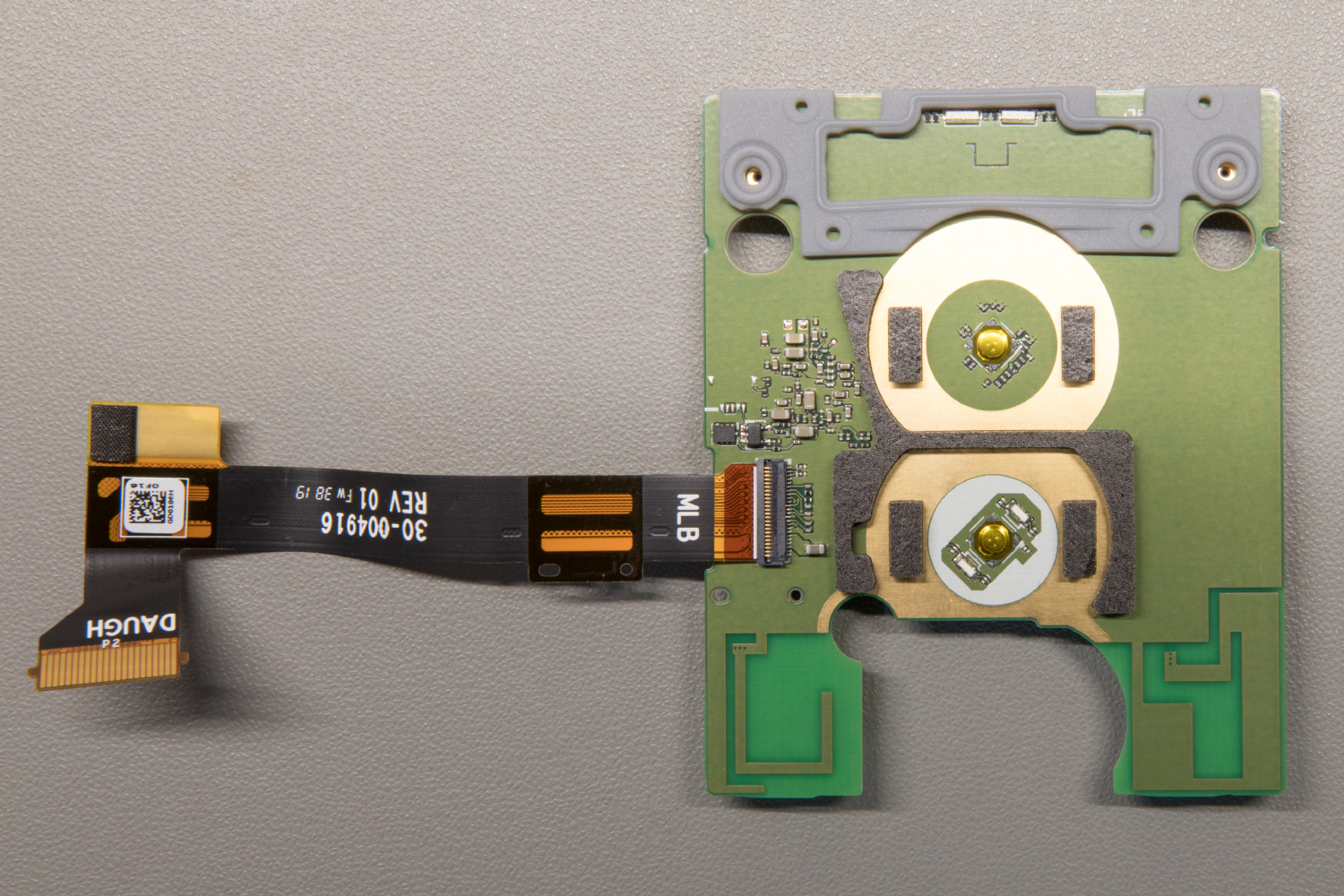
Processor Board
The processor board contains the components for audio input and output, CPU and memory, LED output, wireless communication and power regulation. Most of the components on the Echo Flex are the same as those used on the Echo Dot and Echo Input so it looks like Amazon is reusing the same parts on most of their devices to save on design and build costs.
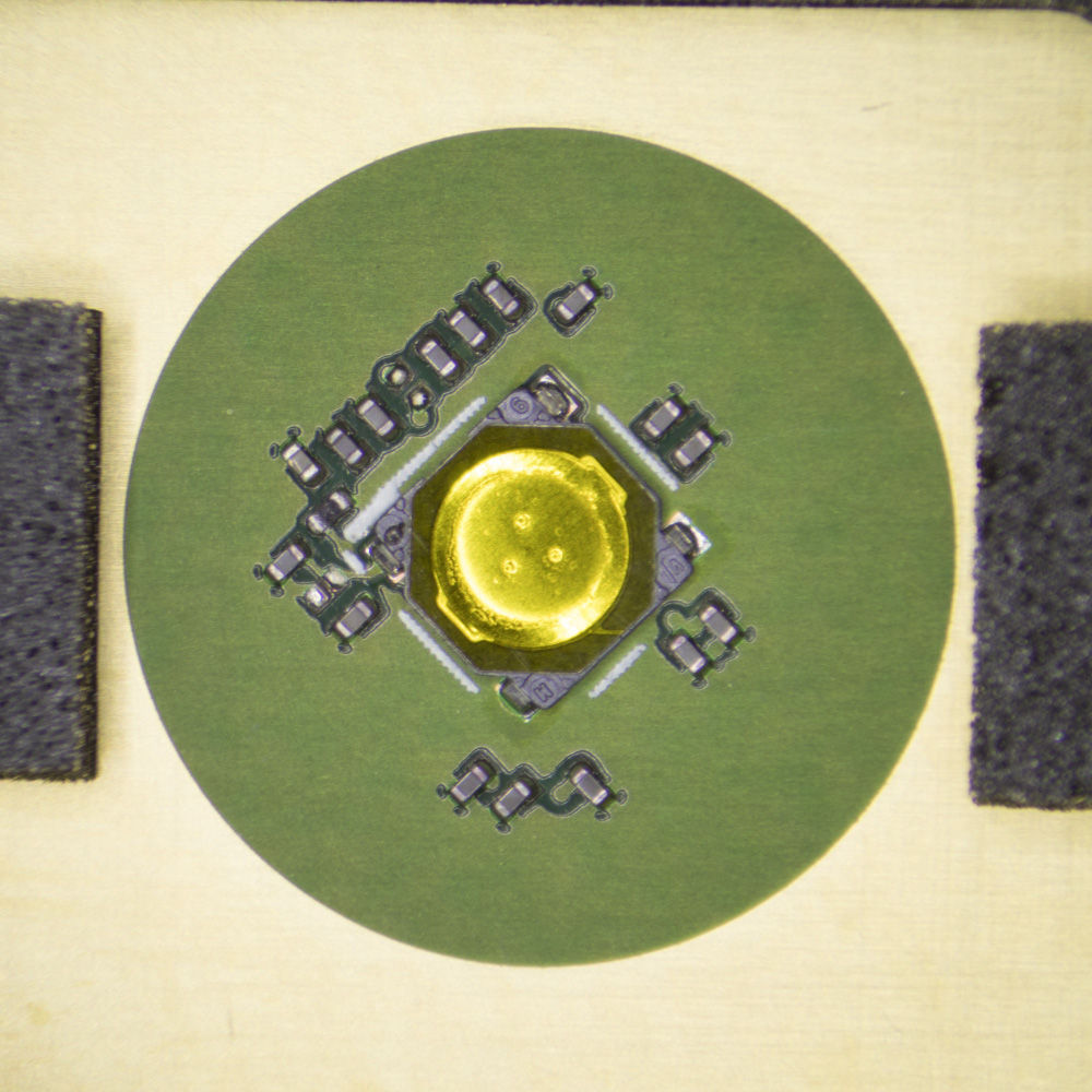
The outer-facing side of the processor board contains the connector for the flat flex cable, two push switches, 2 LEDs, 2 small ICs and a bunch of capacitors and resistors. The Bluetooth and Wi-Fi antennas are also etched into this side of the PCB either side of where the USB connector sits.
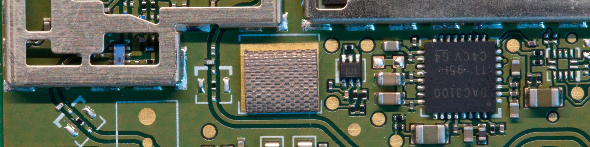
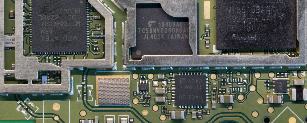
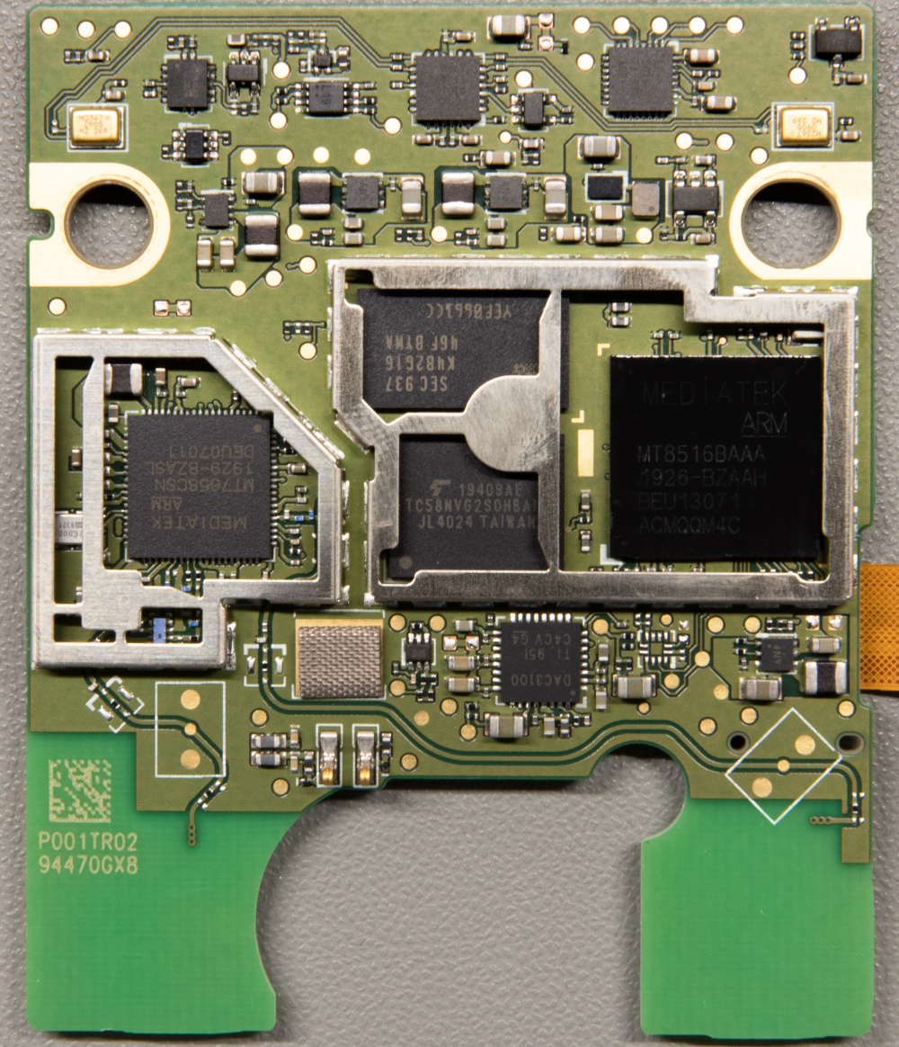
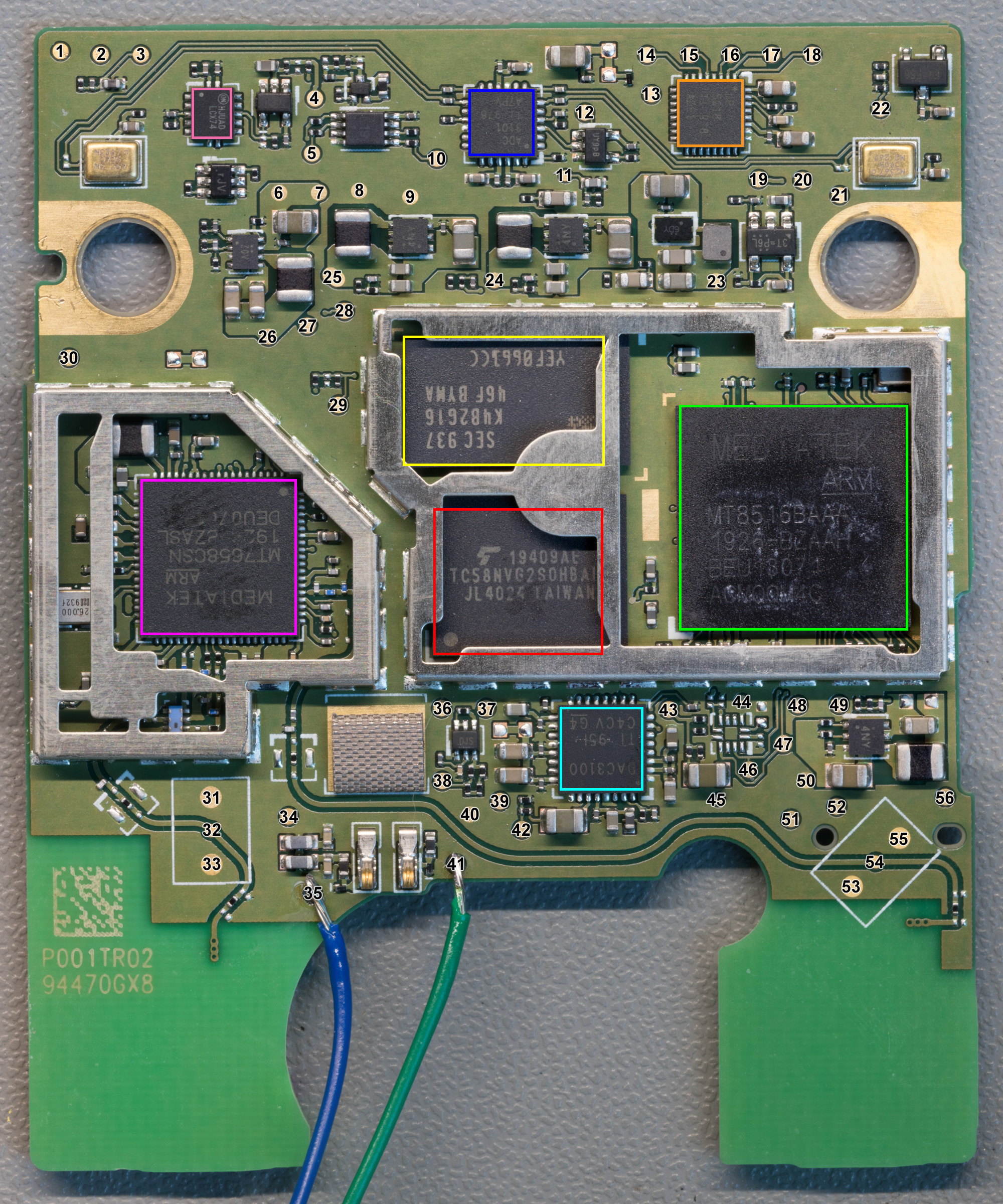
The bulk of the components for the Echo Flex can be found on the inner-facing side of the processor board. To make identification easier the main components have been marked on the photo below with coloured squares.
Starting from the top left corner is a microphone marked M2367 0905 M2 269. Nothing could be found online about this device, but it looks like a surface-mounted MEMs microphone. There is a second identical microphone on the top right corner of the board and they both connect to the ADC.
Next to the microphone is a 74LCX74 dual flip flop (pink outline). On the Echo Dot, the flip flop was used for switching the state of the mute button and it looks like it has the same function on the Echo Flex.
Audio from the microphones is converted to a usable format using a Texas Instruments TLV320ADC3101 stereo ADC with digital microphone support and miniDSP (blue outline). The TLV320ADC3101 communicates with the CPU using an I2C and I2S bus. I2C is used to configure the ADCs on start-up and the audio stream is sent along the I2S bus. This is the same ADC used on the Echo Dot.
On the top right of the board is an LP5018 from Texas Instruments. The LP5018 is an 18-channel I2C constant-current RGB LED driver and is used to drive the two dual colour LEDs on the other side of the board.
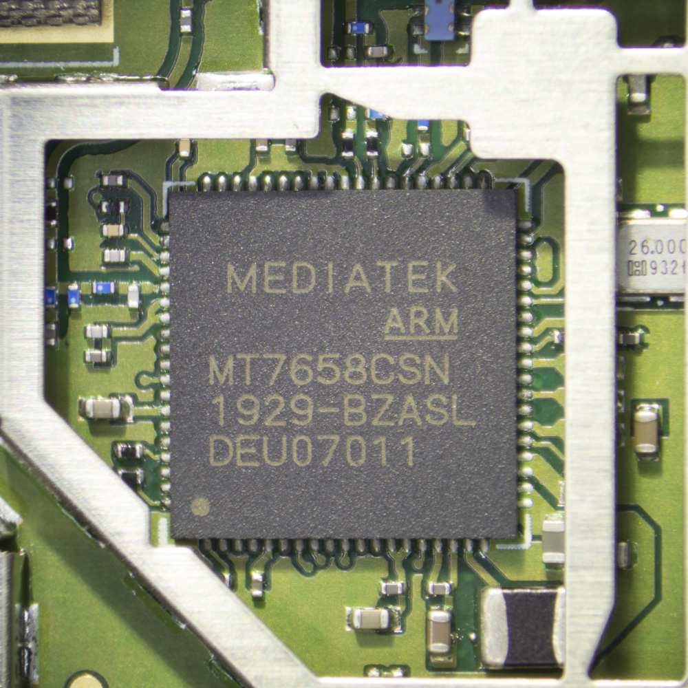
At the centre left of the board is a MediaTek MT7658CSN (purple outline) dual-band Wi-Fi and Bluetooth controller. This controller is designed to be paired with the main CPU and communicates with the outside world. Two PCB tracks route from the MT7658CSN to the PCB antennas on the other side of the board.
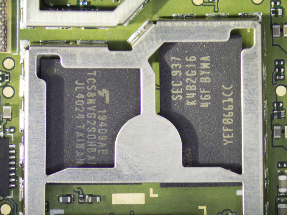
In the centre of the board are the memory chips. A K4B2G1646F-BYMA (yellow outline) 2 Gb DDR3 chip provides the RAM for the CPU and a TC58NVG2S0HBAI4 (red outline) 4 GBIT (512M x 8 BIT) CMOS NAND EEPROM provides the storage for the firmware.
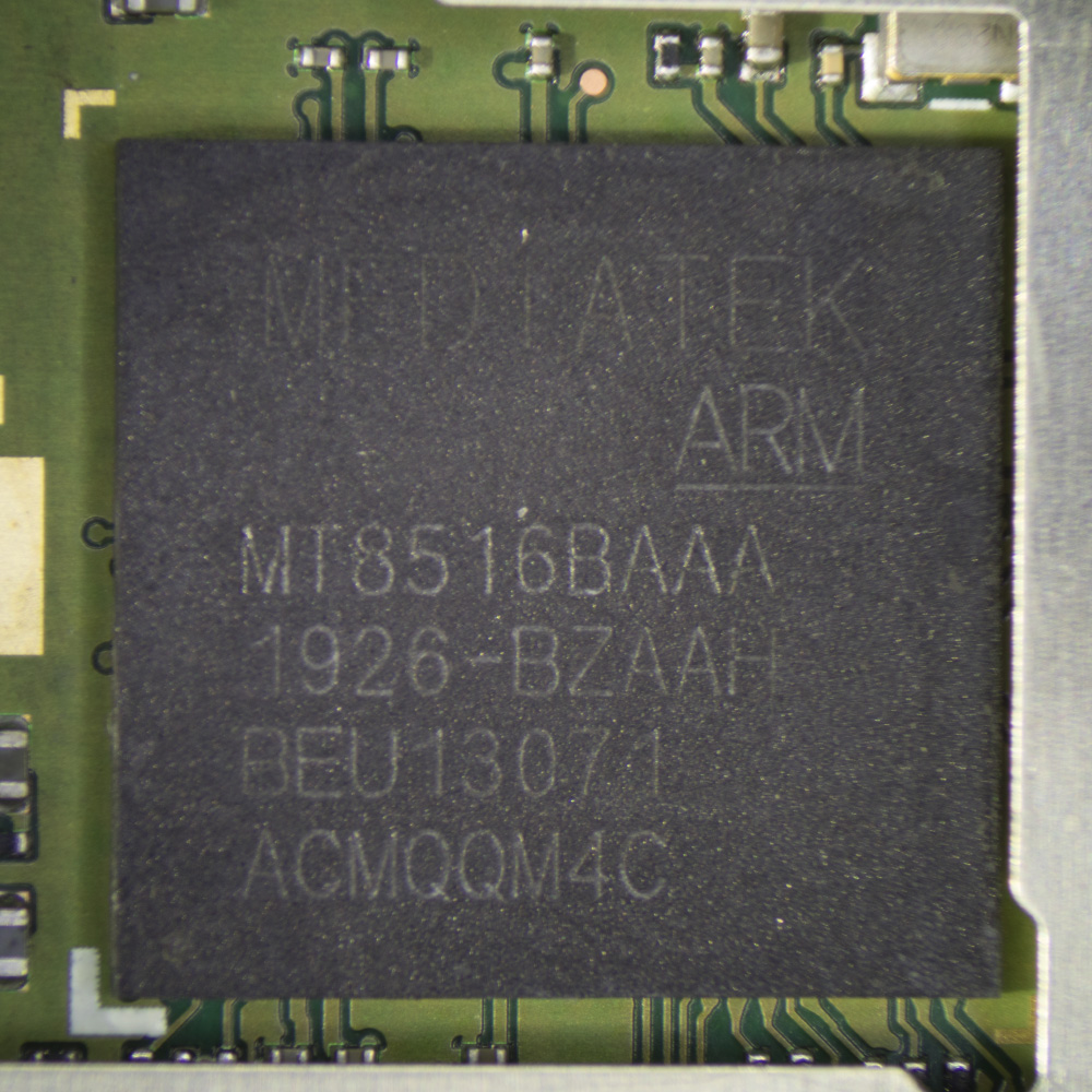
At the centre-right of the board is the main processor. The MediaTek MT8516BAAA (green outline) is the same CPU as used on the Echo Dot and Input. A datasheet for the MT8516BAAA is not available online but according to the marketing info on MediaTek’s website, it is a quad-core, 64-bit ARM® Cortex-A35 core operating at up to 1.3 GHz.
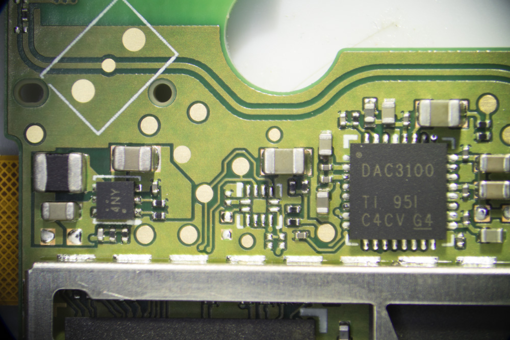
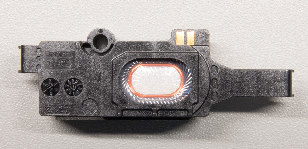
The bottom centre of the board is the audio DAC which provides the output to the speaker. A Texas Instruments TLV320DAC3100 low-power stereo audio DAC With Mono Class-D speaker amplifier. The speaker connects to the PCB using two spring clips.
Alongside the main components are several smaller IC packages that mainly deal with power regulation. Most of them have markings that do not readily indicate what they are, but the three parts marked as 4NY are most likely LN1193 voltage regulators.
The processor board contains 56 test points. After lots of probing with a multimeter and oscilloscope, we were able to determine the purpose of many of the test points. The table below shows a list of the test points and their purpose.
| Test Point | Voltage | Device Connection | Notes |
| 1 | I2C Bus - SCL | LP5018 Pin 29 | |
| 2 | I2C Bus - SDA | LP5018 Pin 28 | |
| 3 | 730mV | ||
| 4 | 3.3V | ||
| 5 | 3.3V | ||
| 6 | 5V | ||
| 7 | 5V | ||
| 8 | Ground | ||
| 9 | Ground | ||
| 10 | 3.3V | ||
| 11 | 710mv | Alexa not responding when probed | |
| 12 | Data | Data from ADC | |
| 13 | 3.7V | ||
| 14 | LED | LP5018 Pin 4 | |
| 15 | LED | LP5018 Pin 3 | |
| 16 | LED | LP5018 Pin 2 | |
| 17 | LED | LP5018 Pin 1 | |
| 18 | 3.7V | ||
| 19 | 2.2V | ||
| 20 | 1.8V | ||
| 21 | 1.8V | ||
| 22 | 1.8V | ||
| 23 | 1.2V PSU | ||
| 24 | 1.8V PSU | ||
| 25 | 1.4V PSU | ||
| 26 | 3.3V PSU | ||
| 27 | 1.024Mhz | 2V Clock Signal | |
| 28 | 16Khz | 1.8V Clock | |
| 29 | 1.8V | ||
| 30 | 720mV | ||
| 31 | Ground | ||
| 32 | Antenna | ||
| 33 | Ground | ||
| 34 | 1.8V | ||
| 35 | Speaker 1 | Audio Output | |
| 36 | 3.3V | ||
| 37 | 24.6Mhz | Clock Signal | |
| 38 | 3.4V | ||
| 39 | 48kHz | 1.8V Clock | |
| 40 | Ground | ||
| 41 | Speaker 2 | Audio Output | |
| 42 | 1.8V | Crashed when probed | |
| 43 | 0V | ||
| 44 | 1.8V | ||
| 45 | 0V | ||
| 46 | 1.8V | ||
| 47 | 1.8V | ||
| 48 | 0V | ||
| 49 | 0V | ||
| 50 | Ground | ||
| 51 | 3.072Mhz Clock Signal 2.0V | TLV320DAC3100 | DAC Audio serial bit clock |
| 52 | Data | TLV320DAC3100 | DAC Audio serial data input |
| 53 | Ground | ||
| 54 | Antenna | ||
| 55 | Ground | ||
| 56 | 1.2V |
Components
USB FastBoot
On the Amazon Echo Dot, there were two test points that could be connected to a USB cable for updating the firmware using FastBoot.
The Echo Flex contains a USB type A socket so to test if the same FastBoot method was available on the Flex we purchased a USB type A plug to type A plug cable.
The Echo Flex was turned on and the dot button was held down which on the other Echo models put the device into FastBoot mode. After several seconds the LED turned green indicating that it had booted into the correct mode. With the device booted the Linux command “lsusb -v” was run giving us a list of USB devices connected to the computer and in the list was a Mediatek device with the following details.
Bus 001 Device 002: ID 0bb4:0c01 HTC (High Tech Computer Corp.) Dream / ADP1 / G1 / Magic / Tattoo
Device Descriptor:
  bLength                18
  bDescriptorType         1
  bcdUSB               2.00
  bDeviceClass            0 (Defined at Interface level)
  bDeviceSubClass         0
  bDeviceProtocol         0
  bMaxPacketSize0        64
  idVendor           0x0bb4 HTC (High Tech Computer Corp.)
  idProduct          0x0c01 Dream / ADP1 / G1 / Magic / Tattoo
  bcdDevice            1.00
  iManufacturer           1 MediaTek
  iProduct                2 Android
  iSerial                 3 xxxxxxxxxxxxxxxxx
  bNumConfigurations      1
  Configuration Descriptor:
    bLength                 9
    bDescriptorType         2
    wTotalLength           32
    bNumInterfaces          1
    bConfigurationValue     1
    iConfiguration          0
    bmAttributes         0x80
      (Bus Powered)
    MaxPower              256mA
    Interface Descriptor:
      bLength                 9
      bDescriptorType         4
      bInterfaceNumber        0
      bAlternateSetting       0
      bNumEndpoints           2
      bInterfaceClass       255 Vendor Specific Class
      bInterfaceSubClass     66
      bInterfaceProtocol      3
      iInterface              4 fastboot
      Endpoint Descriptor:
        bLength                 7
        bDescriptorType         5
        bEndpointAddress     0x01  EP 1 OUT
        bmAttributes            2
          Transfer Type            Bulk
          Synch Type               None
          Usage Type               Data
        wMaxPacketSize     0x0200  1x 512 bytes
        bInterval               0
      Endpoint Descriptor:
        bLength                 7
        bDescriptorType         5
        bEndpointAddress     0x81  EP 1 IN
        bmAttributes            2
          Transfer Type            Bulk
          Synch Type               None
          Usage Type               Data
        wMaxPacketSize     0x0200  1x 512 bytes
        bInterval               1
Device Status:     0x0001
  Self Powered
Running the command "fastboot getvar all" returned the following:
root@echodev:~$ fastboot getvar all > fastboot.txt
(bootloader) 	antirback_tee_version: 0x0001
(bootloader) 	antirback_lk_version: 0x0001
(bootloader) 	antirback_pl_version: 0x0001
(bootloader) 	lk_build_desc: 674eac9-20190926_204255
(bootloader) 	pl_build_desc: 2b6f82c-20190926_204255
(bootloader) 	secure: yes
(bootloader) 	prod: 1
(bootloader) 	otu_code: xxxxxxxxxxxxx
(bootloader) 	unlock_status: false
(bootloader) 	unlock_code: xxxxxxxxxxxxxxxx
(bootloader) 	serialno: xxxxxxxxxxxxxxxxxx
(bootloader) 	max-download-size: 0x8000000
(bootloader) 	kernel: lk
(bootloader) 	product: CROISSANT
(bootloader) 	version-preloader: 0.1.00
(bootloader) 	version: 0.5
all: Done!!
finished. total time: 0.049s
As with the other two Echo devices, we have disassembled the Echo Flex has a locked boot loader so without an unlock code and scatter file it would be impractical to update the firmware on the device.


Chirag A
May I request you to email me the pictures of the SMPS/Power supply section which converts AC to DC voltage
thank you & appreciated!
FRANK ENGELMAN
Very well done. I have the US version and also found the torq screw under the label.
Doug blair
Thank you so much for the break down. Could you tell me which antenna is WiFi and which is Bluetooth. I want to install an external WiFi
antenna
Doug
Brian
Doug, I am sorry but I don’t know which antenna on the pcb is for the WiFi
David
Is there any kind of reset button inside?
Mine is less than 6 months old & dead. No lights, no signs of life. This is the US version.
Mark
Great tear down. Thanks for taking the time and effort. I have one question. I want to put one of these in a UK bathroom but don’t want to introduce mains electric. There is no reason why the plug and associated PSU circuit could be removed and the 5v DC supply fed from a USB type wall adapter in the next room?
Sean
I have the same question as Mark, if the output from the PSU is 5V then it seems entirely possible that a standard 5V USB would work for power. This would open so many opportunities. Any way you could confirm this for us?
Brian
Mark and Sean, I have taken the flex apart and soldered a pair of wires to the 5V power connector from the power supply and the board does power up and run. The power draw on boot is up to 450mA on boot and 350mA when the device is speaking.
Giacomo
Do you now the rating in mA of the embedded power supply?
Brian
Giacomo, the power supply dosn't have any markings to show its output current rating.
Xavier
Do you happen to know the speaker wattage? I am looking to upgrade it if possible
Brian
Xavier, I don't know the speaker wattage, I also do not know if the built in sound chip would be suitable to drive a larger speaker
Marcel
Awesome teardown thanks for doing that, it showed exactly what I wanted to know + your answer on using another power supply is so helpful. I will build the Flex into A Geneva Lab Speaker from the CD age and give it a new life. I was gonna use an Echo Dot but this will work fine and hopefully the 3.5mm jack supplies good sound quality.
Giacomo
Marcel, that's a really nice idea. I think I'm gonna try to smartify my old CFD G50 :D as soon as the Flex is again on sale.
Marco
is it possible to buy a new flat flex connector online?
Simon
The inbuilt PSU is made by Lite-On Model PA-1120-12AN Rated as 5.15v @ 2.4A
Simon
I wanted to run this without the daughter board to make as thin as possible and use lineout.
With the daughter board unplugged using the PINS from your diagram:
Pin 42 = HEADPHONE LINEOUT LEFT
Pin 43 = HEADPHONE LINEOUT RIGHT
Pin 44 = SWITCHES SPEAKER LINEOUT
Pulled up to approx 1.8V via 10K Resistor for Speaker Out
Pulled down to GND via 1K Resistor to enable Line Out
With nothing connected to pin 44 you get line out, maybe best to pull down with a 10K so it's not left floating?
Jochen
Great teardown !
May you have some information about the flex add-ons?
Having a smart clock for the echo flex - trying to find out the protocol used between echo flex and smart clock. For that i plugged the smart clock into a windows pc, a new USB Serial Port (COM3) was discovered.
Is there any documentation about the protocol available ?
Thanks.
JR
Could you share the dimensions of the boards and of the power supply?
I would like to give it a new housing to make it an inwall device, but I am limited to about 55mmx55mm. the deapth is variable though. but the main board needs to fit this square. I don't need the speaker, so I guess this part can be cut off.
Thank you very much!
Brian
Hi, I am sorry but I don't have the Echo Flex now.
JR
Thank you Brian for your reply.
Ich just realized, that on the bottom of the board are the antennas, and cutting them off wouldn't be the greatest idea, so the height, will not fit...
I will have to figure something else out, I guess...
Aaron
Has anyone seen any information about the protocol to talk to the USB interface for devices? I have used the IR sensor to switch on lights when I enter a room and it is great. I would like to be able to connect my own devices and sensors to cause effects with Alexa devices by emulating the IR sensor.
Gavin
Thanks for all the details here, really useful.
I'm trying to do something similar to Simon and run this without the daughter board connected but I do want to use the on board speaker out. I can't work out which/where the pin 44 mentioned that switches this actually is. Can someone please clarify where this is?
Gavin
OK so I worked it out, it's test pad 44, I was confused by 42 and 43 not matching what was in the table.
So it works pulling 44 to 1.8v via a 10K resistor but while trying to solder to pad 44 I've managed to rip it clean off.
Anyone know another point I can pull up to achieve the same effect?