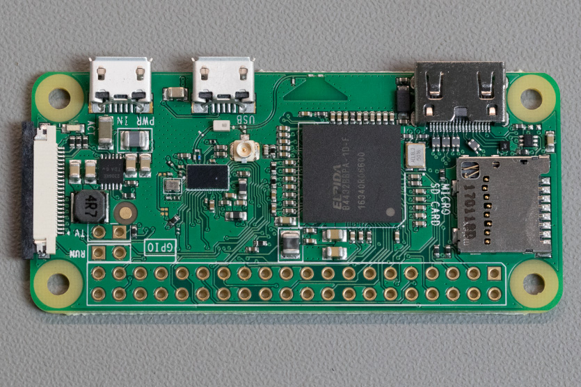
With the release of the new Raspberry Pi Zero earlier this week we ordered one from The Pi Hut to use with our development boards (they all work without any problems) and one from Pimoroni to use with our barcode scanner project. There is a blog post for the Raspberry Pi Zero 2 W which was released in 2021
The new Raspberry Pi Zero W has built-in Wi-Fi and so we thought this would be better than the USB dongle which we are using with the barcode scanner.
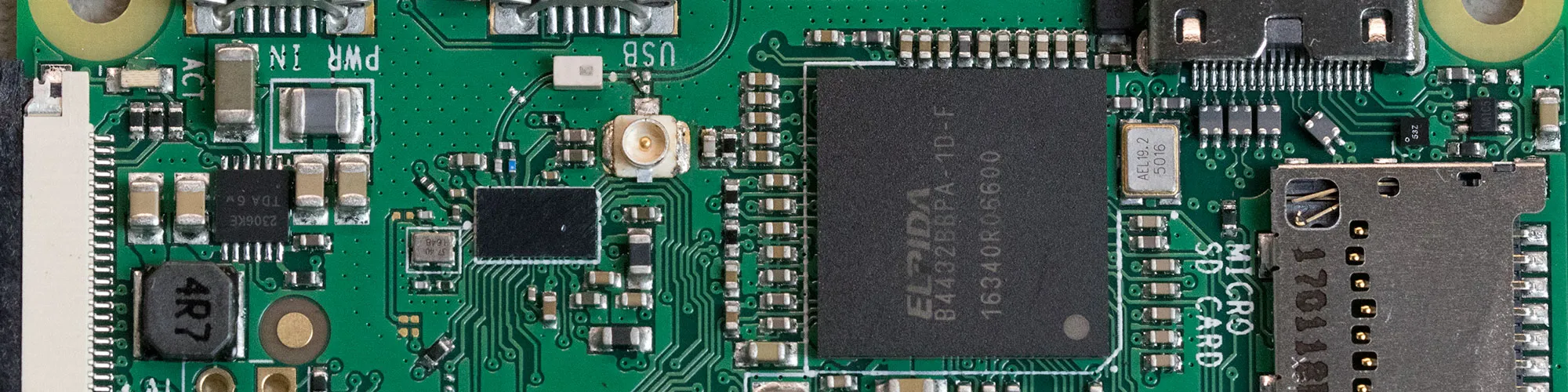
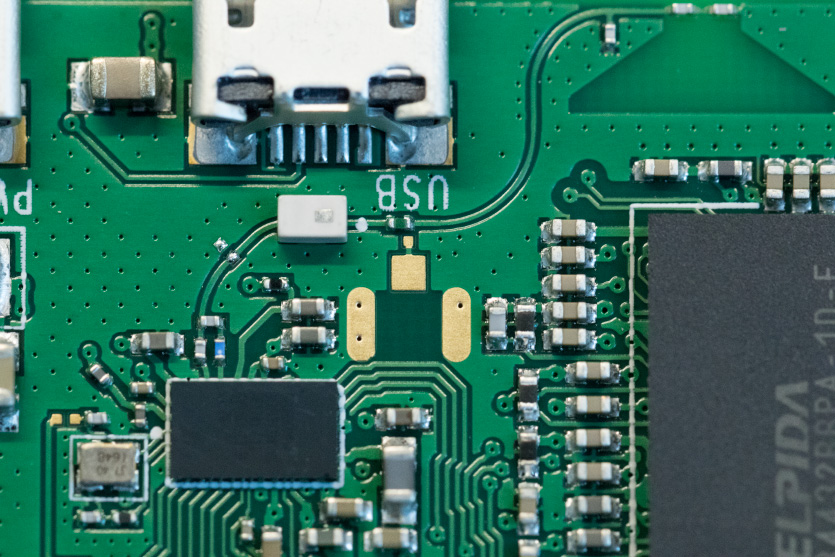
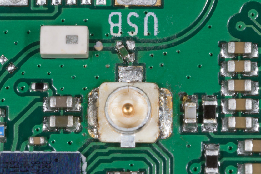
Upon receiving the new board we noticed that the Raspberry Pi foundation has left a space and jumper pad for a U.FL RF connector to use with an external antenna.
Connector Pads
We already had a suitable Wi-Fi antenna and so we ordered the U.FL connector and a short coaxial cable assembly from Farnell.
The parts ordered are:
HIROSE(HRS) U.FL-R-SMT-1(10) and MULTICOMPR-134G7210150CA
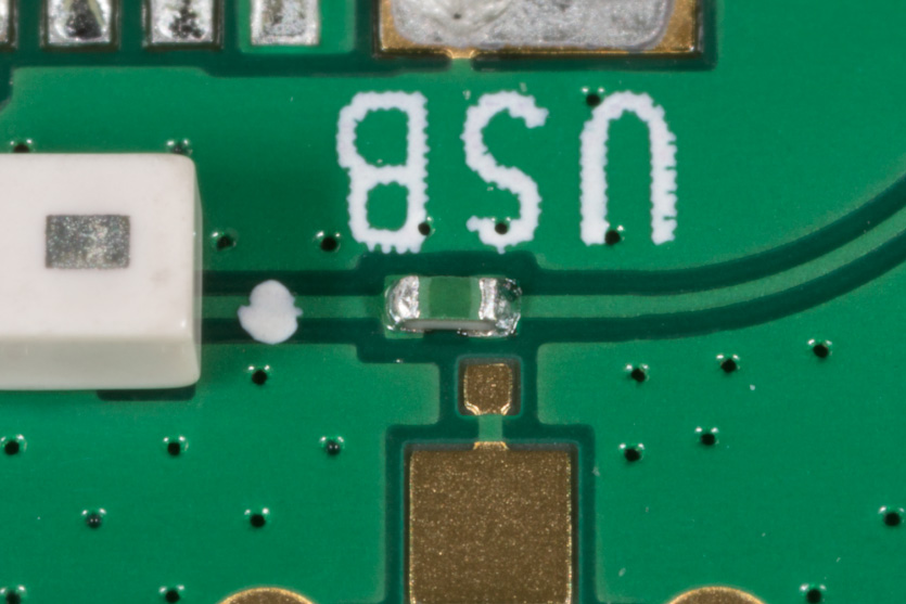
On the Raspberry Pi PCB, there is a component which appears to be a zero ohm resistor (0201 size 0.6mm x 0.3mm) which links to the PCB antenna or can be turned 45 degrees to link to the U.FL connector bypassing the internal antenna.
Component to rotate
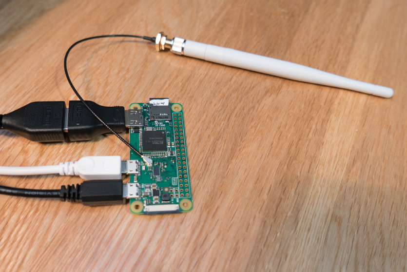
We carefully removed and rotated the resistor to the U.FL link pad and then soldered the new U.FL connector to the board.
The link rotated and the new U.FL connector was fitted.
The connector fitted to the Raspberry Pi Zero W
To test the new external antenna compared to the built-in PCB antenna we used the following command to scan for available Wi-Fi networks.
sudo iwlist wlan0 scan
The following table shows a list of networks found and their signal strength and quality readings. Most networks showed an improvement with the new external antenna and our home network had a much greater signal strength.
| Internal Antenna | External Antenna | |||||
| Network | Channel | Encryption | Quality | Signal Level (dBm) | Quality | Signal Level (dBm) |
| Net1 | 6 | WPA2 | 26/70 | -84 | 27/70 | -83 |
| Home network | 13 | WPA2 | 50/70 | -60 | 68/70 | -42 |
| Net2 | 1 | WPA2 | 27/70 | -83 | 37/70 | -73 |
| Net3 | 1 | WPA2 | 27/70 | -83 | 37/70 | -73 |
| Net4 | 6 | WPA2 | 26/70 | -84 | 27/70 | -83 |
| Net5 | 6 | off | 27/70 | -83 | 30/70 | -80 |
| Net6 | 1 | off | 31/70 | -79 | 37/70 | -73 |
| Net7 | 11 | WPA2 | 28/70 | -82 | 29/70 | -81 |
| Net8 | 6 | WPA2 | 27/70 | -83 | 26/70 | -84 |
| Net9 | 11 | off | 28/70 | -82 | 31/70 | -79 |
| Net10 | 1 | WPA2 | 27/70 | -83 | 25/70 | -85 |
| Net11 | 6 | off | 28/70 | -82 | 23/70 | -87 |
| Net12 | 6 | off | 26/70 | -84 | 22/70 | -88 |
| Net13 | 6 | WPA2 | 28/70 | -82 | 21/70 | -89 |
| Net14 | 11 | WPA2 | 29/70 | -81 | 32/70 | -78 |
| Net15 | 11 | WPA2 | 14/70 | -96 | ||
| Net16 | 1 | WPA2 | 30/70 | -80 | ||
| Net17 | 1 | off | 30/70 | -80 | ||
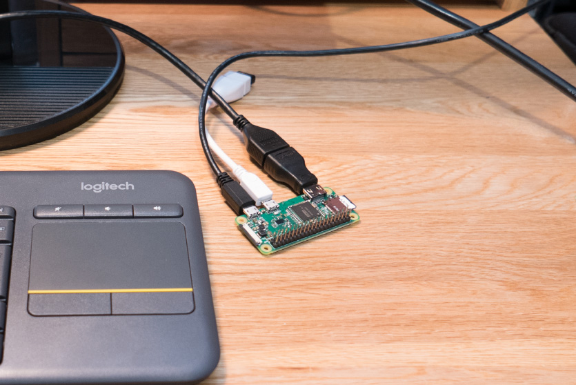
Testing the Raspberry Pi Zero W with the built-in antenna
Testing the Raspberry Pi Zero W with the external antenna
Please note this will invalidate the FCC certification.
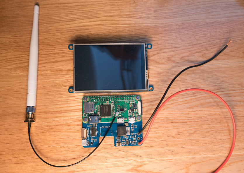
The photo below shows the new modified Pi attached to the Barcode scanner project we are working on. The Raspberry Pi Zero W is mounted between the power supply/controller PCB and the touch screen so the onboard antenna would be shielded by both boards.


cgioconda
It's fantastic that they included a place on the board to solder the component. Very thoughtful!
Myself248
If you look carefully at the pad arrangement, it's more likely that the u.fl jack was there so the onboard resonant antenna could be connected to external test equipment for tuning. Removing the pads in the final board rev would've affected the tuning, so they left it. Using it for this purpose only requires moving the component 90 degrees, and it fits properly across the pads once you've done so. The 45-degree arrangement is clearly not what the pads were designed for, but it serves a purpose that's more useful to the end-user.
Daniel Bull
Its probably more likely that it was there for diagnostics and not removed. Although I do agree its quite useful that they left it there :)
Lotus
It's actually there as a requirement for certification/regulatory testing. A conducted RF port is needed on the final product.
Daniel Bull
Thats Lotus, thats good info, well worth knowing.
OMGWTFZPMBBQ
Also in my experience RF stuff is static sensitive, so please be careful!
Maybe someone can figure out how to use the now-redundant internal antenna for triangulation or similar?
On certain chipsets its possible to specify antenna I or II so it might be feasible ?
Brian
The link resistor allows you to use the built in antenna or redirect the RF signal to the U.FL socket by turning the resistor 45 degrees
OMGWTFZPMBBQ
Ah. My bad, sorry. I see that the internal antenna is basically a special cavity inside the board so each unit is "tuned" correctly although the handy feature here would be further fine tuning using a tiny drop of UV set glue for those times you can't quite fit an external antenna in the unit. Protip, this is also handy for patching up damaged USB-micro connectors after resoldering, adding pink LEDs in place of the vanilla green/yellow and other micro-soldering mods.
Andrew
Nice! However you should also probably change your Wifi network to not use ch13 (Google wifi channels for more info).
Till O'Rrly
Only in the USA. There you can use it to hide you WiFi :)
Brian
I can not find anything that says that i can not use channel 13 in the UK, seems only the USA don't allow it?
Mike Petonic
Nice find! Thanks for sharing... This could come in very handy for some of those iOT applications in remote parts of the house that the W is going to fit into.
Colin Russell Conway
Shouldnt be too difficult to sort out a spdt switch, like on the redbear labs IoTpHAT https://redbear.cc/product/ Although I'm not sure about any that would fit directly instead of the 0 ohm resistor I'm not sure if longer traces might have a negative effect.
Steve Mann
The zero-ohm resistor is common in mass-produced boards where machines do 99% of the assembly. in through-hole assembly we would have used a simple jumper.
NIT
Excellent Tutorial, and nice photos.
Johan
Nice mod. I have a question. Do you think that the bluetooth module also uses this antenna and thus would get its range increased as well?
Brian
I think the bluetooth module must use the same antenna and so its range would also increase.
oscbex
Thanks for excellent tutorial. You're not breaking against any regulations if you for example create a packet sniffer. Then there is no Tx so you can add a 30dBi antenna if you want. For transmission, I also doubt the radio chipset that sits there at the moment gives 20dBm. It's very common in for example phones that Wi-Fi gives maximum 14-17dBm in Tx mode (compare with up to 2W for cellular radios, but those use power adjustments while the Wi-Fi Tx power is on a constant level). Question: is it possible to squeeze an SMA connector on to that pad rather than a UFL? Don't like UFLs. They come off easily.
Brian
I don't think a sma would fit on the pad, but you could use a short ufl to sma socket lead and then glue the wire to the board to stop the ufl connector from coming away.
earth1000
This really is a great idea and should be a factory-feature. I am going to be mounting my Pi Zero in a fully sealed aluminum enclosure, and I need a coax connector at the outside for an antenna. This article was VERY useful.
ch2i
Interesting to see that external antenna does not works "far much better" than the original.
When you tested the external antenna, it was like on the pictures, not up/down like a normal antenna? That may explain small difference?
Steve Mann
Since the Pi-ZW is certified as an FCC Part 15 device (https://fccid.io/2ABCB-RPI0W), any antenna must be an integral part of the device and not user-changeable.
From the Part 15 regulations (47 CFR 15.203 Antenna Requirements)
"... each Part 15 transmitter must be designed to ensure that no type of antenna can be used with it other than the one used to demonstrate compliance with the technical standards. This means that Part 15 transmitters must have permanently attached antennas, or detachable antennas with unique connectors. A "unique connector" is one that is not of a standard type found in electronic supply stores."
Technically- it is an FCC violation to modify the antenna. In the real world, nobody knows if you peed in the pool.
xeone
Hi I have a small question I lost the resistance by desoldering. I wanted to know the value of the resistance to be able to replace it
Brian
It is a zero ohm resistor to link across the pads.
Robert Morgan
@Steve Mann
But, if you're a licensed amateur radio operator, you have license in the 2.4ghz band, and wifi transmitting is then covered under Part 90 rather than Part 15.
Fun to know.
Rafa_RGB
What about doing in some oter way?....
For not so "precise" soldering:
Removing the "dummy load" resistor and coils near the trapezoidal area, then "bridge" the two connections (pcb antenna and connector for the external).
I think it will make thing easier for thos without microscope. ;)
OkinSama
Since it's just a 0 ohm resistor, do you even really need it? You could just remove it and put a piece of wire to patch over.. Or even leave it and add the wire in as well, I mean, cause is there any harm in having both antenna's attached at the same time? lol
Brian
OkinSama, If the resistor was left in place giving two antennas it would cause an rf impedance mismatch on the driver circuit which could damage the WiFi chip.
Aaron
I found your article by accident... Had a zero w idling around here and had the opportunity to get all parts for 8€ locally...
I hammered everything together with a 50€ el'cheapo soldering station and a 10x Watchmakers magnifying glass.
??
All in all, took me less than 15 minutes and my range doubled with a Tp-Link 29cm 8db antenna.
Thanks for the idea :)
Darren Landrum
My interest is not in extending range, but in being able to use a metal industrial case with an external antenna. Is there a solution for this that doesn't violate FCC rules? Thanks!
Brian
Darren, I think adding the external antenna would techincally break the FCC rules but unless you are selling the upgraded boards and cases I don't think you would have any issues.
Joe
Is there anything similar for the Bluetooth antenna? Or is the Bluetooth using the same antenna as the WiFi?
Brian
Joe, I think the bluetooth uses the same antenna.
randy
If anybody's still reading this thread... I want to put a Pi Zero with camera in a sealed tube on the end of a 2-3 meter long 25mm diameter aluminum tube and look at a river bottom (pi + camera moves 20-30cm over river bottom by operator above water holding and moving aluminum tube. Pi+camera will be ~1.5-1.8 meters underwater). Is there any chance that attaching a conductive path from this U.FL RF connector pad to the aluminum tube could bring the wifi up out of the water where I could connect to the submerged pi zero using wifi? (to do ssh and video streaming). If that won't work..any ideas other how to use the aluminum tube to bring up the wifi signal?
Brian
Randy, connecting the antenna to the aluminum tube wouldn't work as an antenna. You would need to use a thin low loss coax cable to connect to the U.FL connector and have an external antenna at the top of the tube. If you search for a "u.fl male to rp-sma cable" you will be able to buy ready made cables and then use a 2.4Ghz antenna on the end of the cable out of the water.
Nic
Hi Brian,
What's the range with this antenna? Could i do FPV flying with a drone? If not, which antenna could you recommend?
Thanks!
Brian
Nic, I am not sure if the range would be good enough for using with FPV and a drone. I recommend looking at dedicated drone antennas like https://www.dronersguides.com/drone-antenna/
Randy
hi Brian,
So would these components match your suggestions?
- U.FL to solder onto Pi Zero https://www.aliexpress.com/item/32884629308.html
- adapter to coax and antenna: https://www.aliexpress.com/item/33023259995.html
- coax cable...whatever I have lying around, old TV or radio coax?
Randy
Brian
Hi Randy, The links for the connector and antenna would work on ok the Pi Zero. The coax needs to be 50 ohm coax and the correct size for your connectors.
Paula
Hi Brian,
I want to improve wifi communication in the field (outdoor - with cellphone signal limitations). I have several options, but I am sure in to use wifi from raspberry pi zero w. It is possible to improve the data rate and range with this antenna if I connect in the another point a gateway based on a Hotspot without a cell signal?
mikepl
Even if not for dB gain it could be used for bypassing design constrains. My project uses all-metal enclosure and having possibility of connecting *any sort* of external antenna saved the day!
David Pickering
Who gives a flying f**k about FCC rules or CE rules for that matter? UK (where the PI originates from) has different certification methods. Also it is open to interpretation as ITU GUIDELINES can differ "In-Country". So lets set the record straight: 2.4Ghz WiFi band is ISM and that all secondary users must accept interference from other users. In the USA they have 11 WiFi channels on 2.4Ghz where in Japan they had up to 14. In Europe, generally it was 13 channels. So, if you buy a MacBook in the USA like i did then wonder why it wouldn't see my Access Point (on channel 13) here's the reason (above). Unfortunately it meant having to change the WiFi board for a whitelisted European version.
Like one person commented; no one knows you peed in the pool!
So like 446Mhz and other "CB" radios that are supposedly type-approved blah, blah, you will always get someone "blasting" their signals illegally and get away with it. I suppose it's the radio equivalent of the BMW/Mercedes drivers who overtake everyone, then pull over at the very last second to exit a motorway as an inconvenience to everyone else and they get away with it.
Mark
Maybe V2 of the zero w could have the connector included and provide a jumper to use it? It would be extremely useful and wouldn't void the warranty to use an external antenna either...
John B
Warranty for a $10 device?
Somebody
Could I pay you to do the same thing to my PiZero? My hands are not as steady as I would like.
Dj
Hi,
I just did the same, in hopping to achieve better bluetooth signal strenght, only to get worse wifi and bluetooth signal.
What went wrong?
Any thoughts?
Timm Richter
Hi. When I tried this mod I accidentally knocked off (and lost, argh) the upper component left from the socket in the pictures above. Does anybody know what that was?
Jonny XRay
exactly what i was hoping for ! nice post briandorey !
Real Name
Any chance you could do a blog of the same mod for the new Pi Zero 2 W?
(I don't see a resistor on the new design...looks like you'd just have to jumper the pads to u.FL footprint and cut the trace to the triangle antenna?)
Brian
I am trying to source a Pi Zero 2 W but none of the UK resellers have any stock. As soon as one is available, I will order it and make the mod post for the blog and youtube.
Scott
Re: the Pi Zero 2 W -- looking at the trace leading from the chip past the u.FL pad to the on-board antenna, it looks like there's an in-line resistor or jumper in series at the start of the antenna. I think that might be the one that needs to be moved. https://imgur.com/a/xMfQCQA
Given how hard it is to get one of these right now though, I'm not ready to experiment just yet.
Real Name
Those look like capacitors to me, although I'm only basing that on the colour...
If I have a chance to detect whether they are resistor/capacitor, I will update..
Peter
Does this also work for Pi2 zero? Thanks
Ed van den Enden
Thanks for this great post.
I bought the new Raspberry pi zero 2W and because of the changed layout I wonder if we can still mount an external antenna? Does somebody now?
Thanks
Brian
Ed, there is a link for the new blog post for the Pi Zero 2 W in the first paragraph to briandorey.com/post/raspberry-pi-zero-2-w-external-antenna-mod
4c3T
Kind of odd that the pad leading down to the antenna isn't located (in picture) more to the left so it's right underneath the pad nearest the jumper. Would be interesting to know why. Can't imagine there's any pin jumpers that are designed that way, and putting the jumper in 45° instead of 90° is just weird. It's located right underneath the "wrong" pad, unless it's mean to be connected in parallel with the internal antenna, which makes no sense either. Had there been some filter of some sort so it wouldn't interfere it would've been another matter, but it doesn't look that way.
Might work with both internal and external, or it might now. Don't know, I just find the design, as I wrote, weird.
It would hardly affect performance to move that pad a millimeter or so so that it'll align.