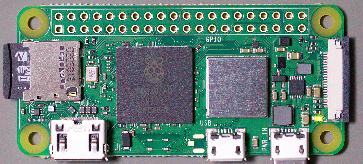
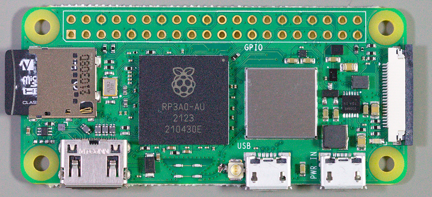
The Raspberry Pi Zero 2 W is the latest board in the Raspberry Pi Zero family, with a 1GHz quad-core processor and 512MB SDRAM and was released on the 28th of October 2021.
When the Raspberry Pi Zero W was released in 2017, we modified the board with an external antenna connector, which was a very popular post. With the announcement of the new Raspberry Pi Zero 2 W version, we tried to order the new board and make the same modification again.
Initially, the very limited stock was available, and we could not order the new board until the end of November.
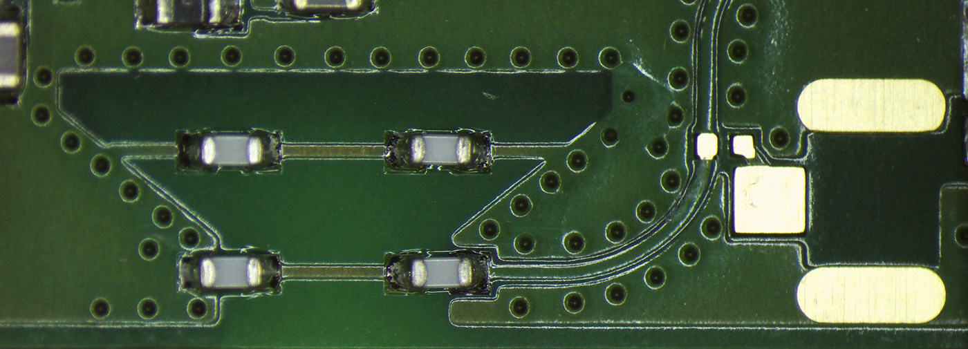
As with the previous version, the Raspberry Pi foundation has left a PCB footprint and jumper pads for a U.FL RF connector to use with an external antenna, but the new Raspberry Pi Zero 2 W has a solid PCB trance going to the built-in antenna compared to the 0201 links used on the previous board.
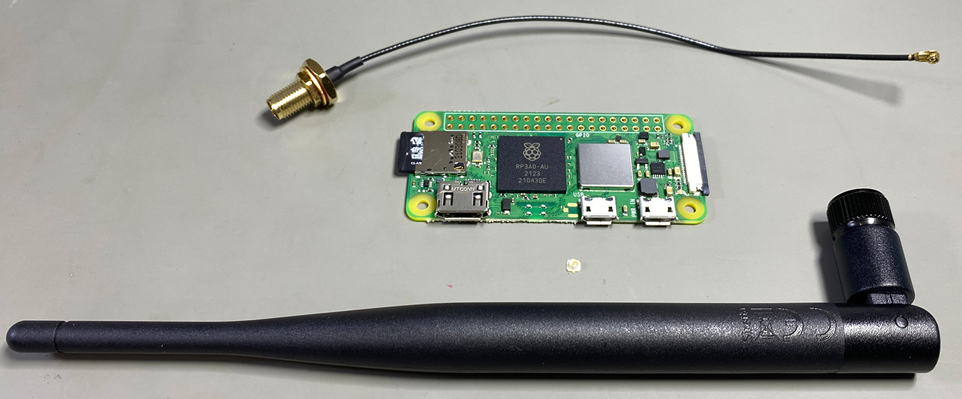
We ordered a suitable Wi-Fi antenna, U.FL connector and a short coaxial cable assembly from Farnell.
The parts ordered are Swivel Type Antenna, U.FL-R-SMT-1 and JF1R6-CR3-4I - RF / Coaxial Cable Assembly.
Before starting the modification, we used the following command to obtain a list of available Wi-Fi networks and their signal strengths and save it to a text file.
sudo iwlist wlan0 scan | egrep "Cell|ESSID|Signal|Rates" > scanlist.txt
Adding the U.FL connector
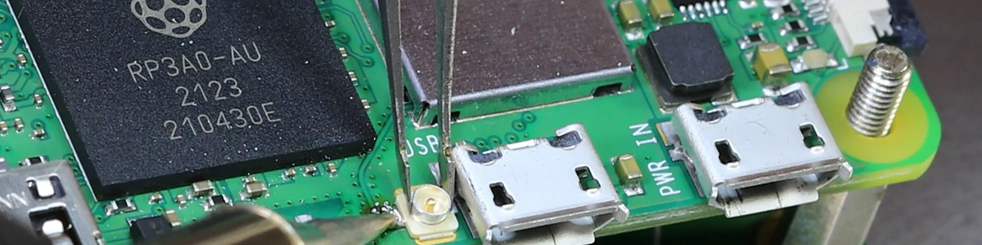
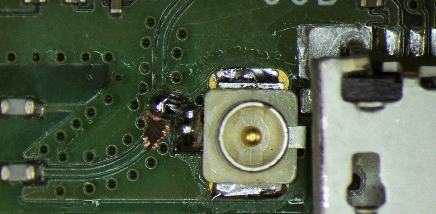
First, we need to cut the track to the PCB antenna. We used a Dremel with an engraving tip, which could also be cut using a sharp knife to scrape away the copper trance. Take care not to cut either side of the track into the ground plane; otherwise, you could cause a short circuit on the antenna circuit. We cleaned the resulting dust away with a cotton swab.
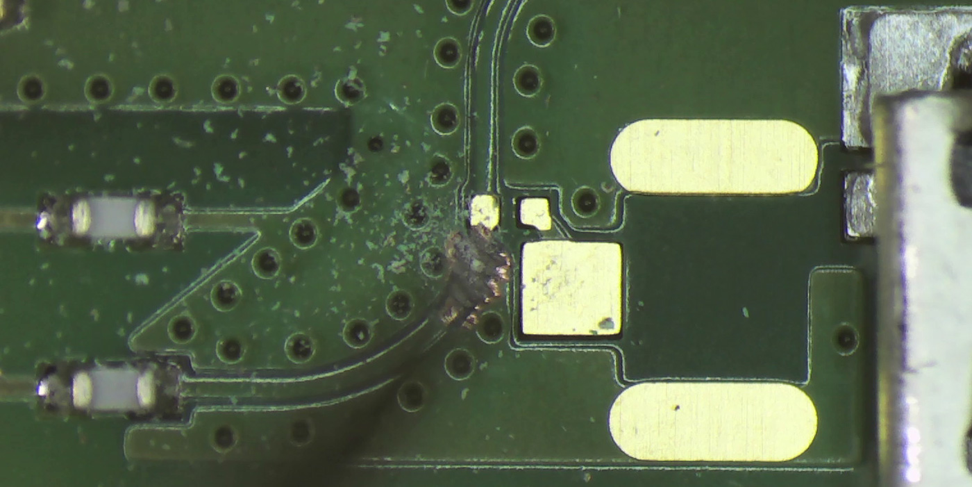
Next, we applied solder to the centre pad for the U.FL connector and to the two small pads to fit a zero-ohm resistor (0201 size 0.6mm x 0.3mm). We did not have a suitable 0201 resistor, so we later created a solder bridge with the soldering iron and a small amount of solder.
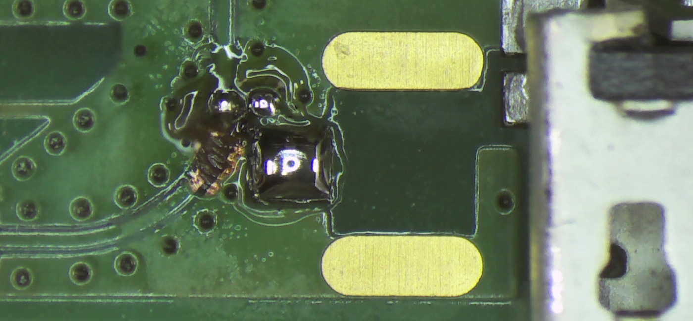
The U.FL connector was then fitted in place and held with tweezers, and the heat was applied using a needle-tip soldering iron to heat the centre pad.
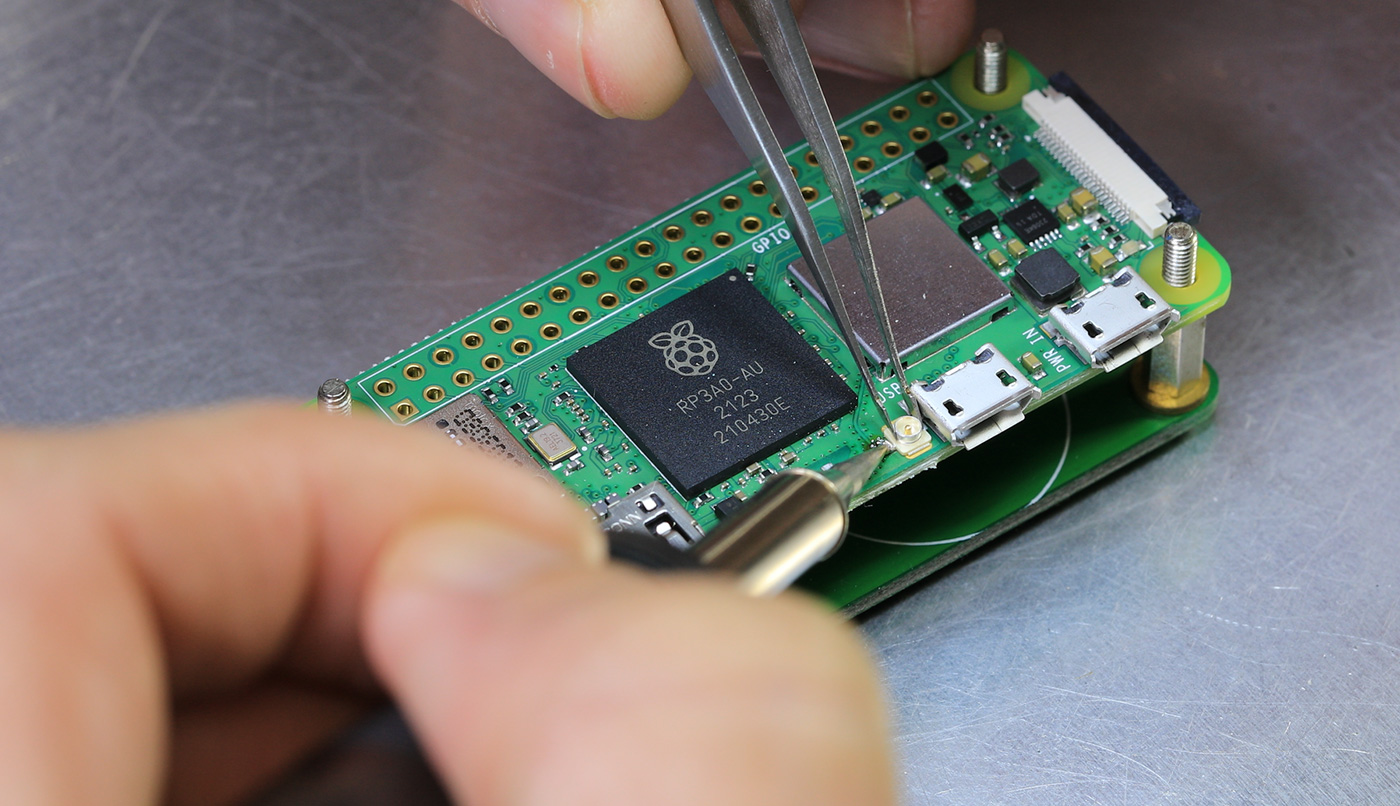
The outer pads are then soldered to the ground plane on the PCB. We tried this with the small soldering iron tip but found that it did not have enough thermal mass to heat the board, so we changed it to a 2mm soldering iron tip to heat and flow the solder fully.
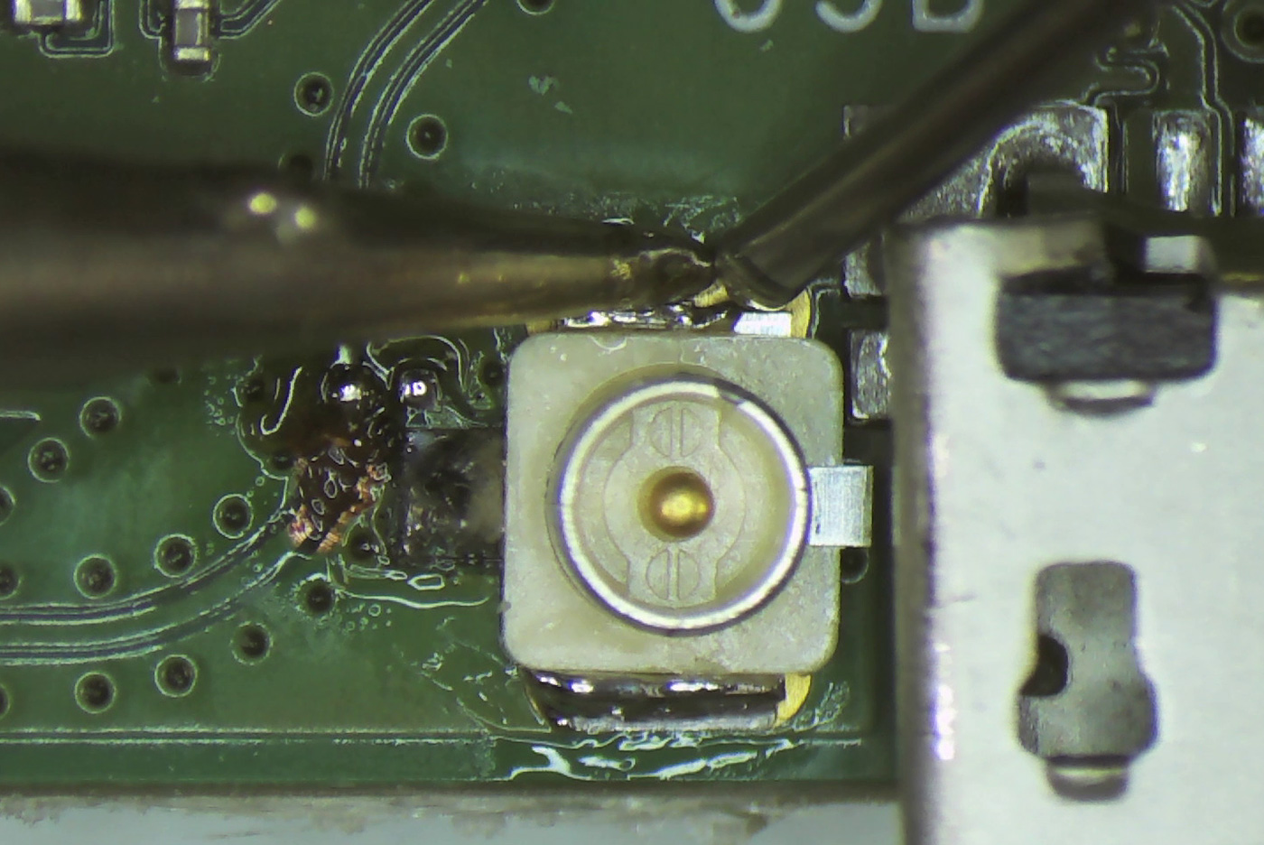
With the connector fitted and the solder link complete, we cleaned the area with a cotton swab and alcohol to remove any solder flux.
Testing the new antenna
To test the new external antenna compared to the built-in PCB antenna, we used the following command to scan for available Wi-Fi networks and saved it to a new text file.
sudo iwlist wlan0 scan | egrep "Cell|ESSID|Signal|Rates" > scanlist-result.txt
The testing was performed in the same location as before, with the new antenna held vertically. The signal strength would improve further if the antenna were fitted to a metal ground plane.
The following table shows a list of networks found and their signal strength and quality readings. Most networks improved with the new external antenna, and our home network had a much greater signal strength.
A smaller Signal Level (dBm) is better.
| Network | Internal Antenna Quality | Internal Antenna Signal Level (dBm) | External Antenna Quality | External Antenna Signal Level (dBm) |
|---|---|---|---|---|
| Home Network | 36/70 | -74 dBm | 44/70 | -66 dBm |
| Nearby Network 1 | 24/70 | -86 dBm | 33/70 | -77 dBm |
| Nearby Network 2 | 25/70 | -85 dBm | 29/70 | -81 dBm |
| Nearby Network 3 | 25/70 | -85 dBm | 29/70 | -81 dBm |
With the PCB antenna, the Raspberry Pi Zero 2 W detected 4 available Wi-Fi networks. After installing the new external antenna, it detected 14 Wi-Fi networks.
The video below shows the modification being made to the Raspberry Pi.
Why not leave the track and remove the component on the antenna?
Several comments have been posted on various blogs asking why we didn’t just remove the first “resistor” on the antenna trace. The component is a capacitor which measures 6.5pF on an LCR meter and is part of the tuned PCB antenna.
Removing the capacitor would create an unmatched impedance to the RF driver, which could cause problems with the signal integrity.
The small curved track, which would be left on the PCB, measures approx. 4.3mm which would be resonant at 17.4GHz at quarter wave (7th harmonic), 34GHz at half wave (14th harmonic) and 69.7GHz at full wavelength (29th harmonic). Harmonics are calculated on Wi-Fi 2.4 gigahertz frequency.


Real Name
Great post, thanks for risking your Zero 2 W to do this mod!
Tim
don't destroy the trace, just move the 0 ohm resistor.
Brian
There isn't a zero ohm resistor on the 2W mode, only on the first gen one.
greetings from Hackaday
Cool! Do you think this could be done by removing the resistor that appears to be inline with the PCB antenna? I personally would be scared to cut the trace :)
Of course, I'm not sure if this would actually work, RF isn't really my cup of tea.
Pat
Leaving the track's worse than you think. The resonant frequency of the stub needs to be calculated in the propagation speed of the wave (on the board) not free space. It looks like CPWG, which means the effective dielectric constant's probably around 2, meaning it's probably around 70% speed of light. So it's actually more like 12 GHz, or the 5th harmonic.
But if I were doing this I'd probably scratch the trace to generate a pad so that I could rotate the resistor there if I wanted to.
greetings from Hackaday
Please disregard earlier message, and -1 to me for lack of research. I think I understand now.
Keith
I am developing a product for a client and the heart of it is the RPi Zero 2 W (yeah, I know... real easy to source in quantity right now)
The problem I am having is the RPi constantly drops the WiFi connection all together and then brings it back and it's worse when the CPU is under heavy load. I have tried messing with WiFi power save features in rc.local and read about adjusting the Group Rekey Interval. I have tried running it off official Canakit supplies (tried the one for the RPi 4b) and I am still having it drop out. I can't have the WiFi drop out at all, it's essential to the product.
Any thoughts on if this would help not only WiFi range, but stability. If it's a firmware issue with the chip, then I doubt this will help me, but I wanted to ask and see what you thought.
Thanks for the guide!
Brian
Hi Keith
We haven't had any issues with the WiFi dropping but if the Pi is getting a low signal the antenna mod should improve the signal strength. This mod will invalidate the RF compliance of the board so could be an issue if you are selling them again.
moscho
@Keith, I've had lot of intermittent problems with WiFi on some of my raspberries just because I did some raspbian versions' full updates by myself and forgot some details in the way. So, in brief and assuming you're using raspbian, check your configuration files, mostly /etc/dhcpcd.conf and /etc/network/interfaces (from the stretch version this one is obsolete and may interfere). Maybe your issues are more system and/or network config related and not an antenna failure.
There are tons of help out there regarding this (very common) situation.
Tetris
Hey Brian, first thanks for the tutorial.
In ,,The component is a capacitor which measures 6.5pF on an LCR meter and is part of the tuned PCB antenna'' you mention the small capacitors which i ripped of the board. Do you know wich one this is exactly? Can you provide me a link maybe?
Thanks in Advance
Brian
I'm sorry but I don't know the value or part number of the capacitors.
Slade
I am looking for a Raspberry Pi Zero 2 w. I am wanting to put it on my generator with a Genmon Gethub software. I have found some Pi 4 and they will work but I am concerned with the heat. I live in the US and Nevada's heat gets warm in the summer. I was told the Pi 4 gets a bit warmer. Do you have any Pi Zero 2 w with external antennas? Could I send you a Pi Zero 2w and have you install the external antenna if you don't have one? Let me know, thanks!!!
Brian
Hi, I am sorry but if we modfiied a Pi zero to add the antenna mod it would not be FCC compliant and be able to be sent to you.
David
Why not use a 201 capacitor (6.8pF?) , the original is D.C. blocked, does the WiFi chip need the D.C. block?
Graham
I suggest using a scalpel (or similar modelling knife with a pointed blade) to cut the track.
Cut through the track (at 90 degrees) at the desired start and finish points, peel the track away from the PCB using the scalpel. The blade can also be used to scrape away the lacquer when fitting the link. The benefit of doing it this way is it (should) result in a neater job, but most importantly you greatly reduce the chances of copper dust/particles potentially causing short circuits as they could be very small.
Hopefully RPi will take the opportunity to modify the Pi's to allow this mod to be done more easily - or even offer it as an option.
dev246
Does anyone know how much of a deterioration it would be to add an external antenna and leave the original internal one intact?
Thomas
I did the mod and it works well but it doesn't seem to pick up 5GHz APs. I thought it would just start doing that automatically but I guess I was wrong.
Did you manage to get 5GHz working with this? I'm not even sure if it's possible, at least not without recompiling the kernel, but I can't find any information on it whatsoever other than a vague reference to recompiling the kernel.
Brian
I didnt try the modded board with a 5Ghz network.