This blog post is part one of a new project we have been working on in our spare time for the past few weeks, a new Raspberry Pi Zero-based wireless barcode scanner with a touchscreen interface.
Part Two of the project is at briandorey.com/post/raspberry-pi-zero-handheld-barcode-scanner-part-2 and part three at Raspberry Pi Zero Handheld Barcode Scanner Part 3
The idea for a wireless barcode scanner was in response to keeping track of all the components we use to manufacture our Raspberry Pi boards which we sell on https://www.abelectronics.co.uk/ and to use when picking customers’ orders from our stock range.
We looked at several commercial systems but none of them would integrate with our e-commerce CMS systems and stock management software and so we decided to try to make our own.
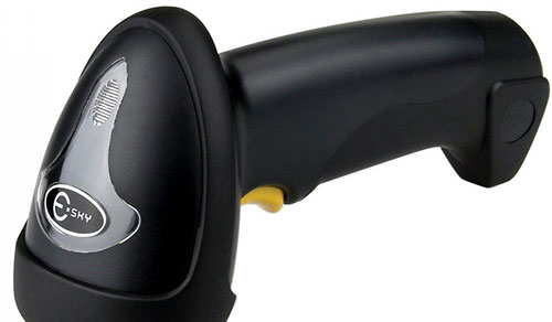
We found a USB barcode scanner from Amazon UK called “Esky ES015 Wired Handheld USB Automatic Laser Barcode Scanner Reader” for only £12.99 and when the scanner arrived we took it apart to see how we could fit it into a smaller case with the Raspberry Pi Zero and the Adafruit PiTFT Plus 480x320 3.5" TFT+Touchscreen for Raspberry Pi (https://www.adafruit.com/products/2441)
The barcode scanner housing.
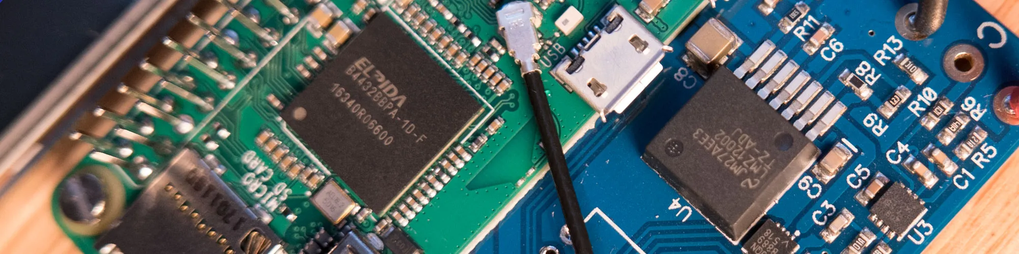
The output from the barcode scanner can emulate a keyboard or can be set in UART mode by scanning the supplied configuration barcodes. The barcode scanner has two internal circuit boards, one with the laser scanner and a microcontroller and an interface board which has the USB, LEDs and button/beeper, plus uart and ps/2 control components. The two boards are connected using a short flat flex cable.
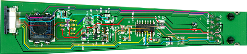
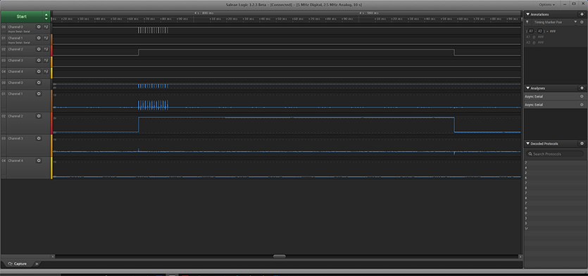
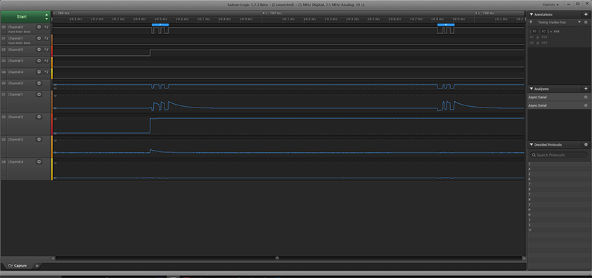
To reduce the size of the new Pi Zero barcode scanner we decided to reverse engineer the barcode scanners interface board to make it much smaller and we did this by using a high-resolution scan of the single-sided interface board and tracing each track between the flat connecting cable and the output pins on the base of the unit. We also used our logic analyser to monitor the UART outputs to see how the data was formatted. The scanner returns a string of characters followed by a return character for each successful scan.
Tracing the connections on the barcode scanner interface PCB.
Data capture from the UART pins on the barcode scanner.
We modified the Adafruit touchscreen to remove the long stacking header and the 26-pin GPIO header and then fitted a lower profile socket which allows the Raspberry Pi Zero to fit very close to the back of the touch screen. A custom interface and power supply PCB will be designed to fit on the back of the Raspberry Pi Zero.
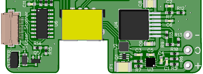
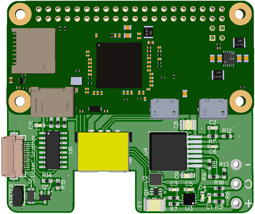
The interface and power board will connect to the laser module PCB via the original flat cable.
The PCB mockup with a Raspberry Pi Zero on the top of the board.
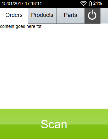
The Raspberry Pi will run a web browser and internal web server to generate the user interface as shown below. This will interact with the hardware to scan barcodes and with remote secure web services to load orders and update stock and component levels.
Part two of the blog post will show the assembly of the hardware and software.
The scanner user interface progress so far running on the Adafruit touchscreen


Brad
Hello! I’m trying to do something similar, but I have nowhere near the resources that you do. I have a project (built successfully 3-4 iterations already) but it requires me to buy a commercially available barcode scanner and rip it the guts, and put the 1d scanner components within a smaller housing. Now I’m hoping to decrease cost (by NOT buy a scanner just to take it apart). I would like to know which components are required if I just want to “build me own” scanner.
Can you help me?
Brian
Hi, I am sorry but I couldnt find a source of the scanner modules on their own and had to buy a complete unit to get the parts needed and usb interface.