In the black Friday sale at Amazon, we purchased an Amazon Echo Input which is a small voice-controlled device that requires an external speaker and uses the Amazon Alexa voice command service.
As this is the second Amazon echo device we have purchased, we decided to take it apart to see what you get for your £15.00.
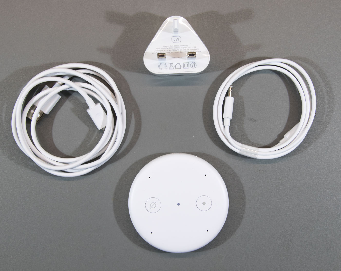
In the Box
- The echo input
- 240V UK power supply
- USB Power cable
- 5mm Audio cable
- Things to try leaflet
- Setup instructions
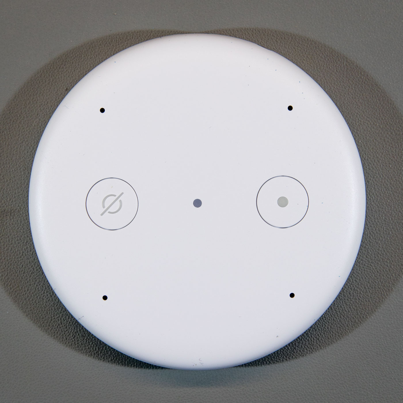
Top of the Echo
The top of the echo input has two buttons, four microphone holes and LED.
Case Base
The base has the serial number, product logos and certification marks.
On the side are a power input socket and headphone/audio out 3.5mm stereo socket.
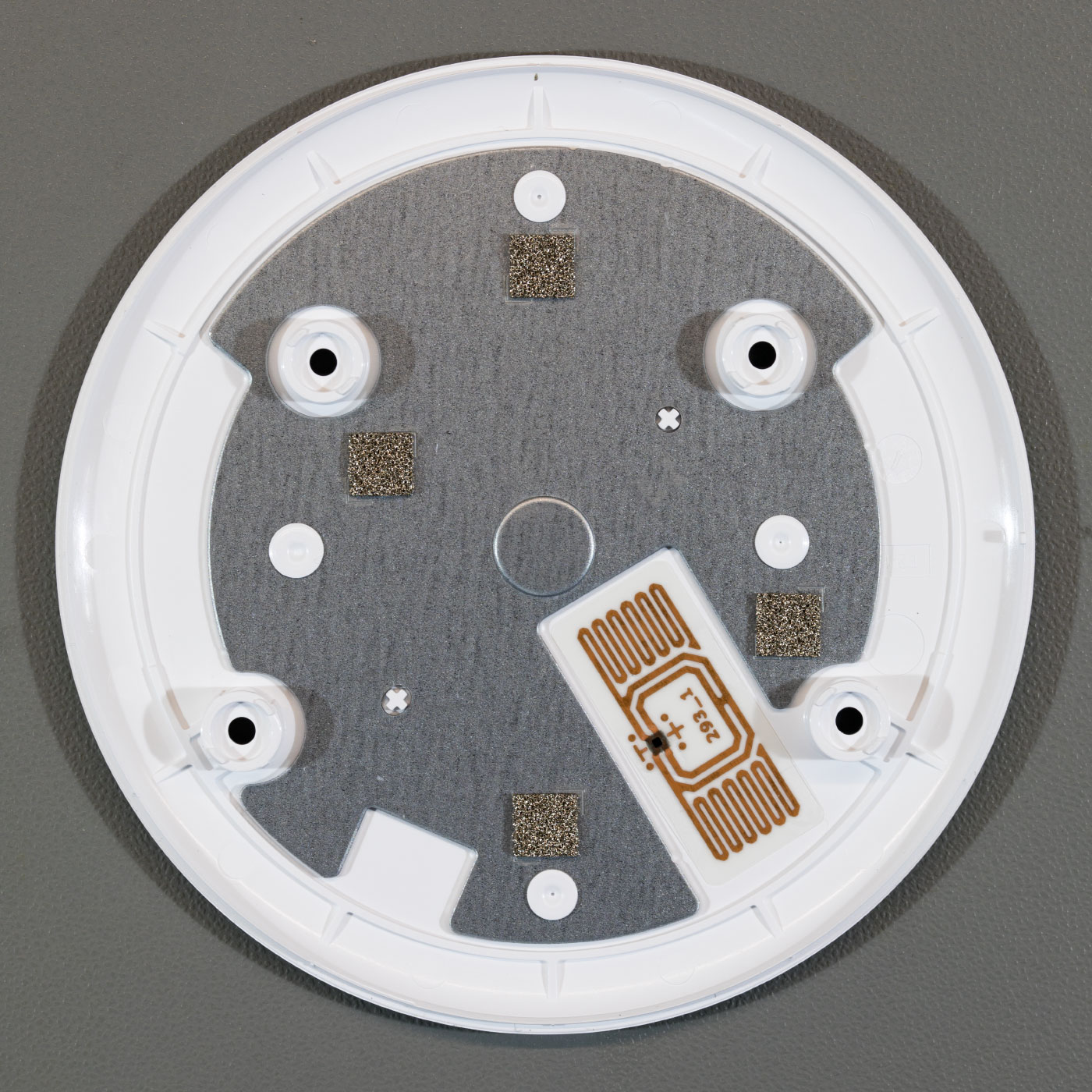
To open the case first you need to remove the rubber non-slip cover on the base of the echo input, using a thin knife or some other flat-bladed tool.
Under the cover, you will find four Torx bolts. Removing the bolts allows you to remove the plastic base which has a metal shield and an RFID tag.
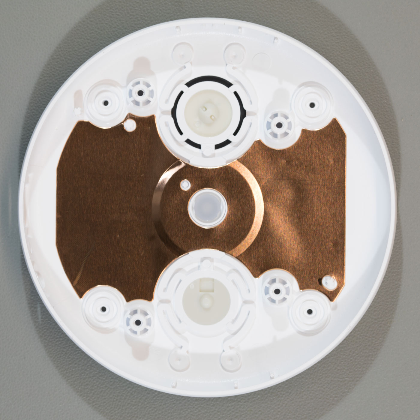
Case Top
Inside the top half of the case is another metal shield. Removing this reveals the main PCB and the top half of the plastic case which has additional metal shielding and the control buttons.
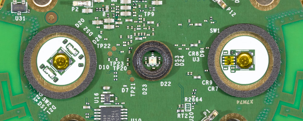
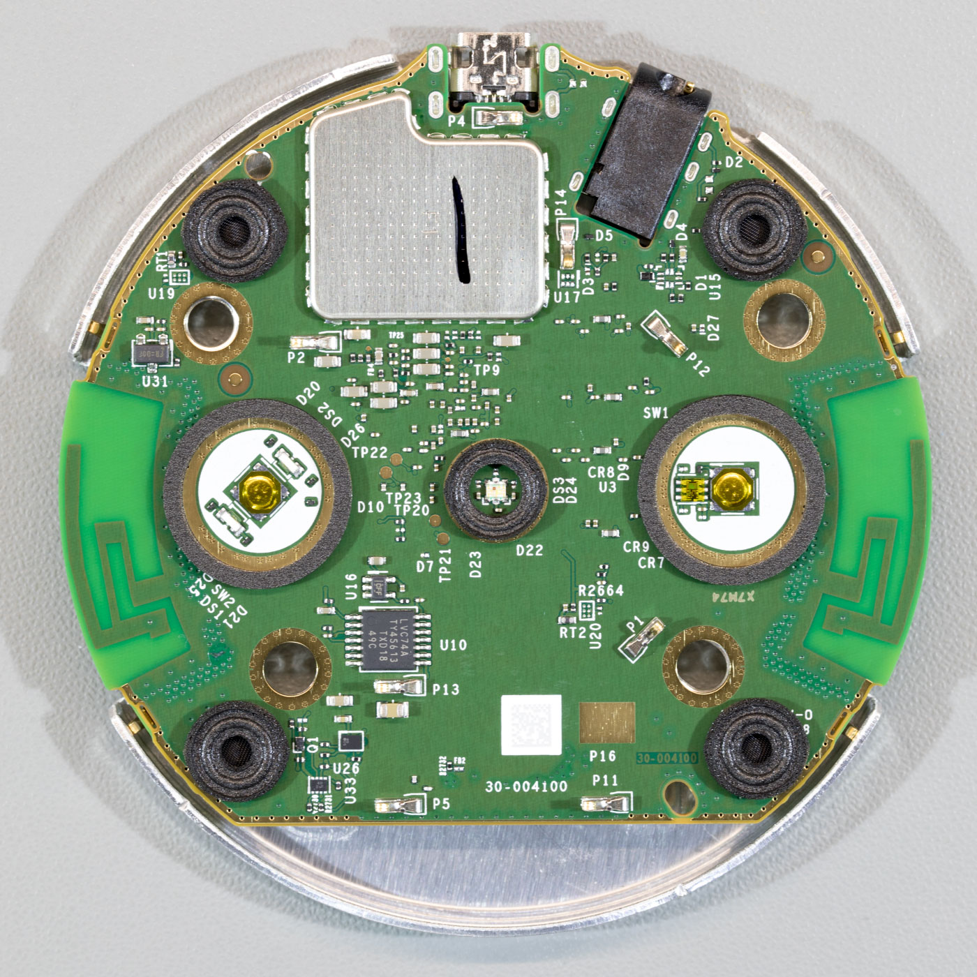
PCB Top
The top of the PCB has two buttons with an RGB LED in the centre.
Next to the left button on the photo below is what appears to be a light sensor IC and there is an LVC74A by Texas Instruments which is a Dual Positive-Edge-Triggered D-Type Flip-Flop.
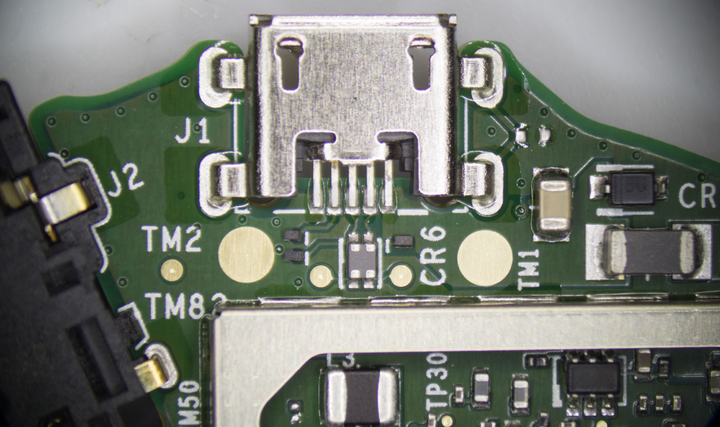
The sides of the PCB have cut-outs that house the 3.5mm audio port and the USB power socket.
There is a small metal shield which covers the 4Gb KLM4G1FETE Samsung eMMC that contains the operating system and other software.
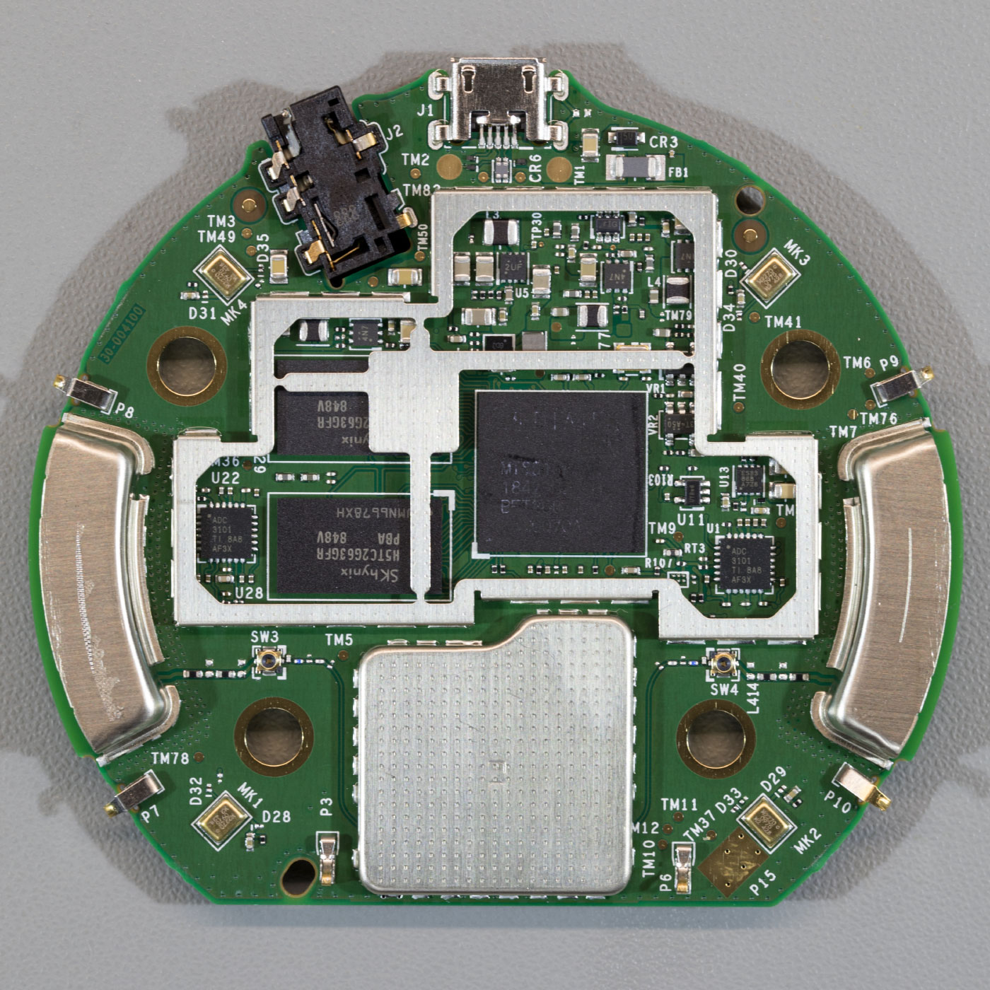
PCB Base
On the underside of the PCB is a large metal shield with conductive pads. Each side has a metal housing which appears to be related to the antennas and a smaller metal shield which houses the Wifi IC.
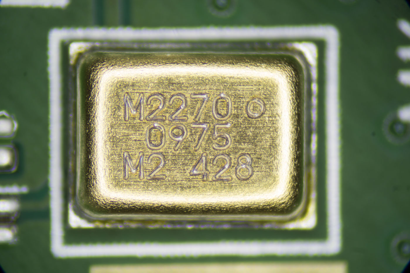
There are four microphones marked M2270 0975.
The large metal shield is removed by unclipping it around the edges. It is also held to the main processor via a heat transfer pad.
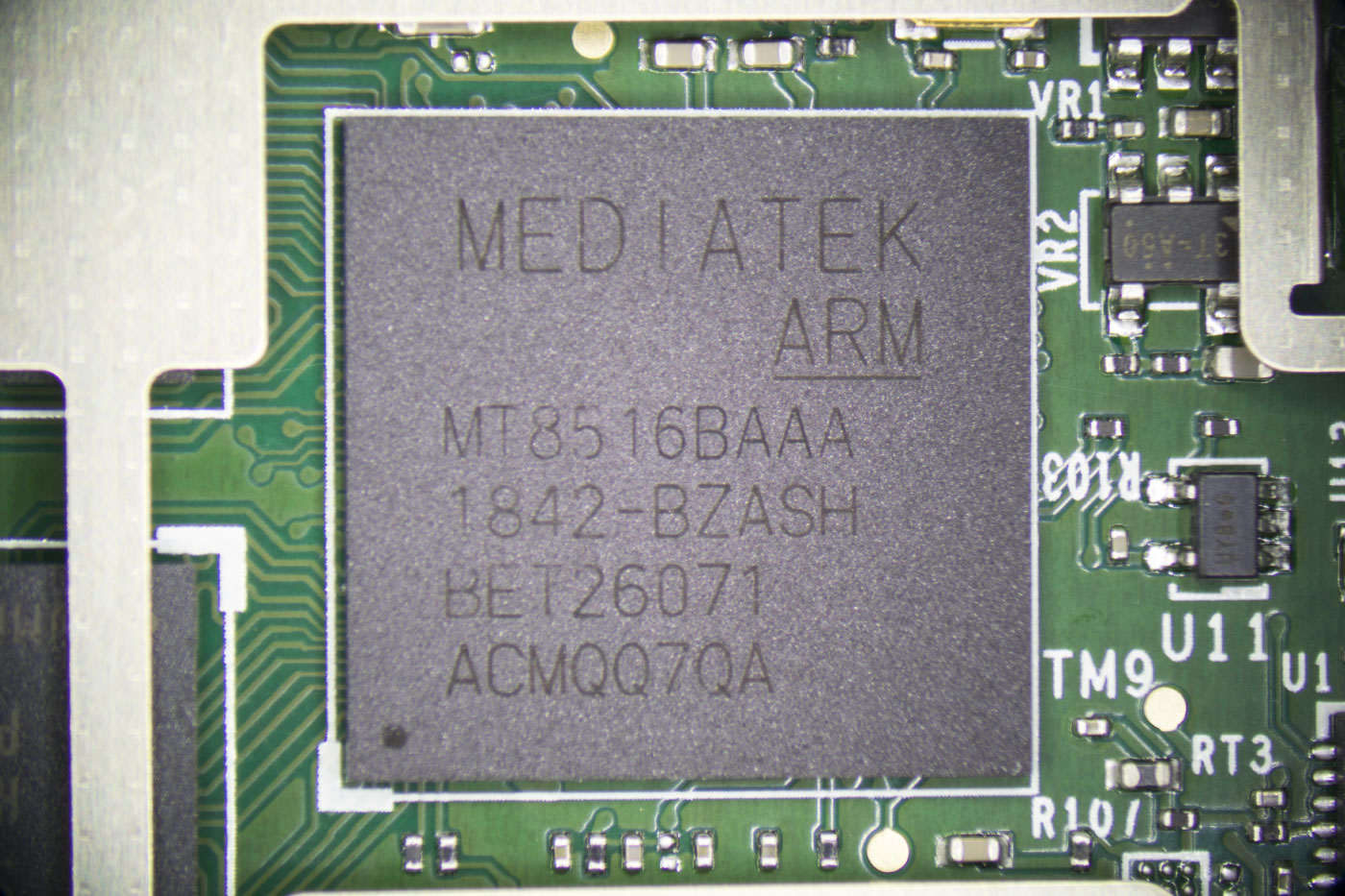
The main CPU is a Mediatek MT8516BAAA ARM 64-bit ARM Cortex-A35 processor which is the same chip used on the Echo dot.
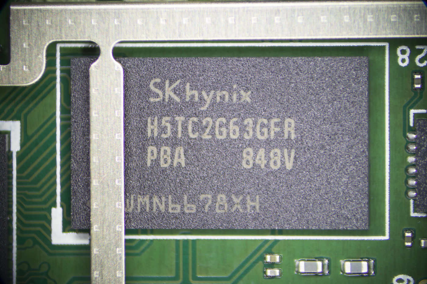
Memory is provided using two Skyunix H5TC2G63GFR 2Gb low power Double Data Rate III (DDR3L) Synchronous DRAM ICs.
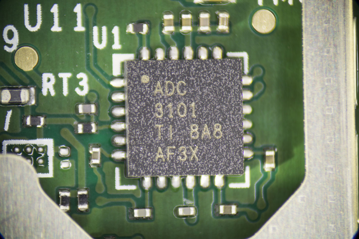
The four microphones feed into two TLV320ADC3101 chips from Texas Instruments. The TLV320ADC3101 is a Stereo ADC with an embedded mini digital signal processor. The Echo input uses the four microphones to locate the direction the voice is coming from and filter out background noise.
Above one of the ADC, chips is a small 8-pin IC marked ES33 868 A7Z6.
The smaller metal shield is removed by melting the solder around its edges.
The metal shield houses the MediaTek MT7658CSN dual-band Wi-Fi and Bluetooth controller with an ARM Cortex-R4 CPU. The MT7658CSN manages communication to wi-fi and Bluetooth devices and connects to two PCB antennas located on the outer edges of the board.
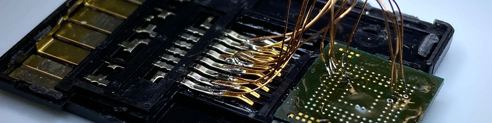
The eMMC Chip
Whilst removing the metal shield which covers the eMMC storage chip, using our hot air reflow station, the chip accidentally came off with the metal. As we don’t have any way to re-ball a BGA chip we thought we would try to connect to the chip to try to access the data on it and see if the content is encrypted or not.
We found several commercially available BGA sockets but these are very expensive and so we looked for an alternative way to access the contents of the chip.
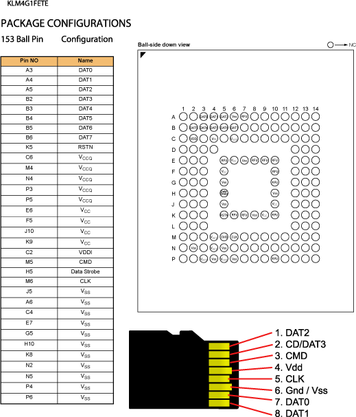
eMMC uses the same communication protocols as SD Memory cards, so we found a pinout for the Micro SD card standard and using a MicroSD to SD card adapter we matched the pins on the Micro SD adapter with the corresponding pins on the eMMC IC. Using some 0.1mm enamelled wire, a new extra fine soldering iron tip and a lot of flux we carefully soldered wires between the SD card adapter and the IC. The eMMC IC is 11mm x 10mm x 0.8mm. 153 pins, 0.5mm ball pitch.
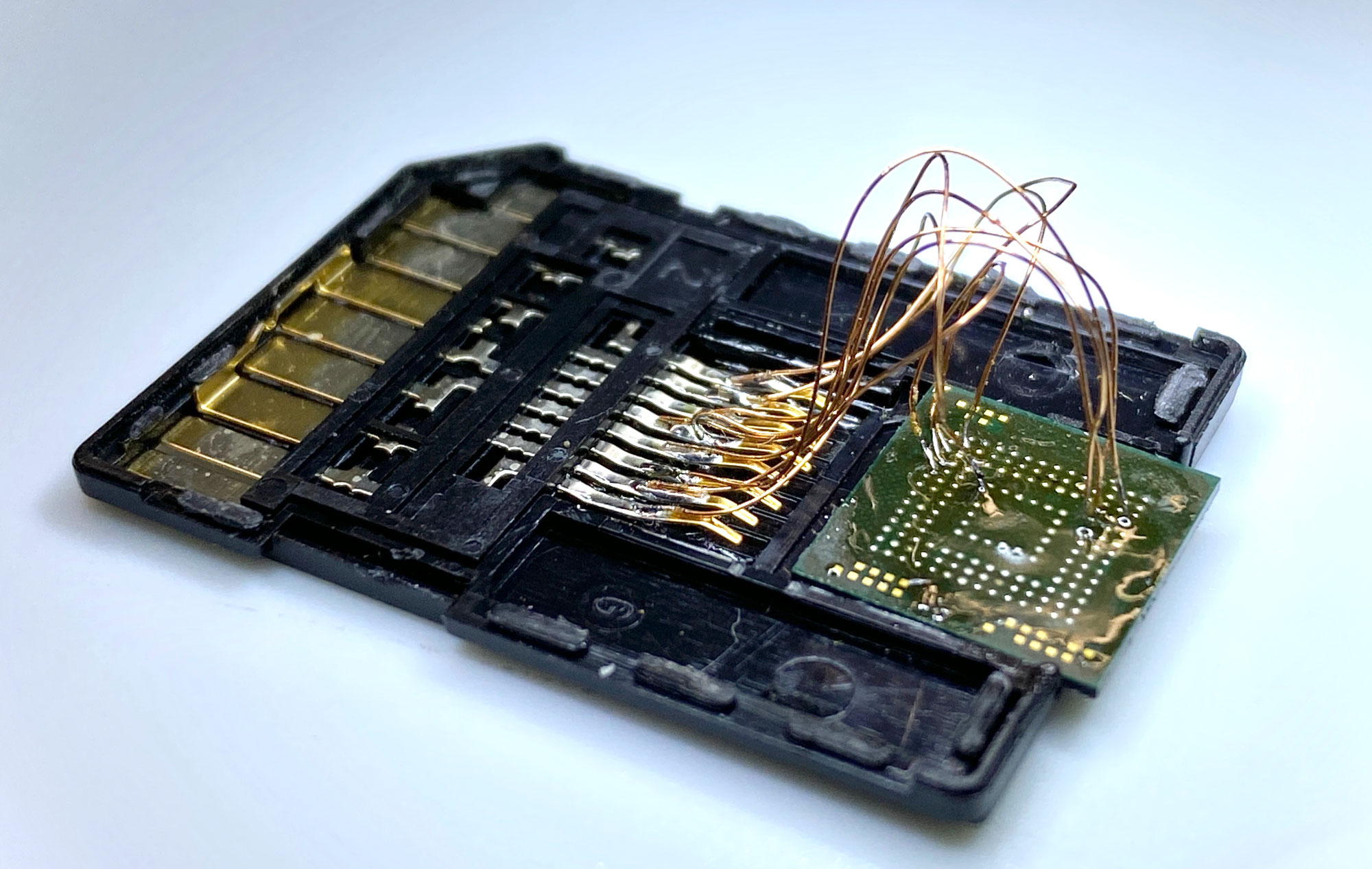
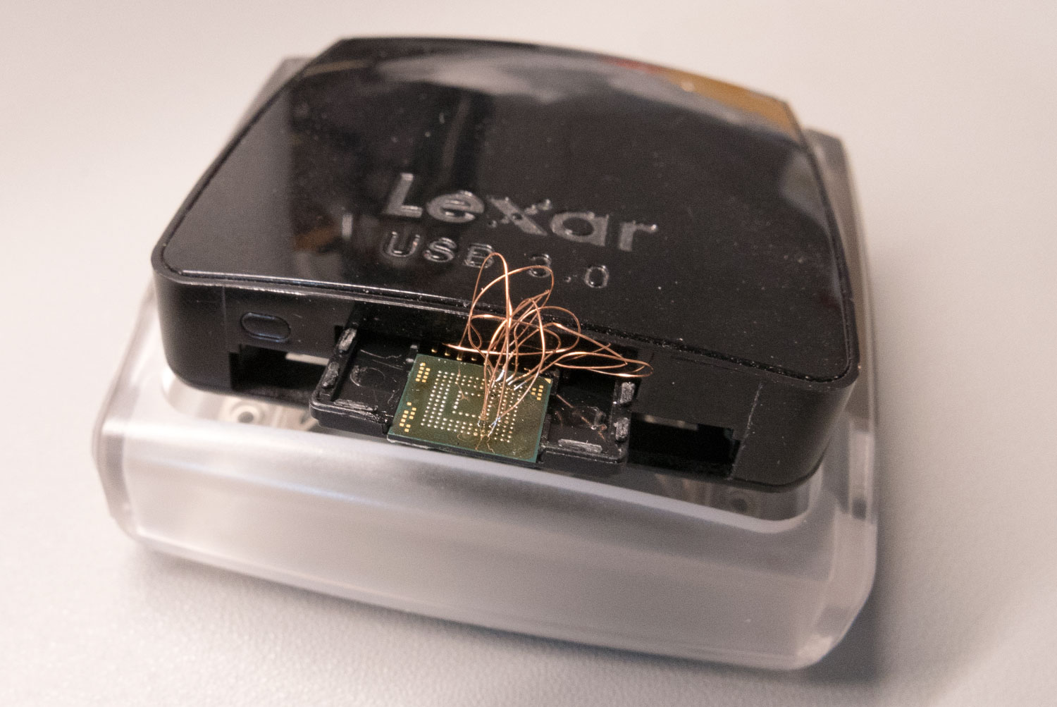
The SD card adapter was then plugged into a USB card reader and connected to one of our Linux computers. Linux automatically mounted several ext4 partitions which indicated that the adapter was working successfully. We then used the Linux tool dd to make a copy of the entire drive to an image file that we could then inspect without risking the original version.
A quick look through the partition structure of the drive indicated that it was an android-based system and after some research online we found that it was based on Amazon's Fire OS. We don’t plan on doing anything further with what we have found at the moment as we don’t have the knowledge to try modifying the contents of the drive or have any way of fitting the chip back onto the PCB but it was a useful experiment in recovering data from eMMC memory chips.
Update 9th December 2019
I have received a lot of messages, criticism and comments on various websites regarding the operating system from the eMMC flash on the Echo Input and why I haven’t posted an image/iso of the operating system online for others to download or provided file lists and screenshots of the folder structure.
The Amazon Fire operating system is a proprietary OS and Amazon does not publish the source files in any form, as the OS is not Open Source, it would be a breach of the Digital Millennium Copyright Act (DMCA) https://en.wikipedia.org/wiki/Digital_Millennium_Copyright_Act for me to post a copy of their proprietary operating system on my blog or other file sharing site.
I do not want my web hosts or myself to receive a DMCA request for the website to be shut down and this is why I am not prepared to share the files.
Components
The following photos were taken using our new microscope and are of various ICs and components on the PCB.
Main Processor
Memory
Control Button with light sensor
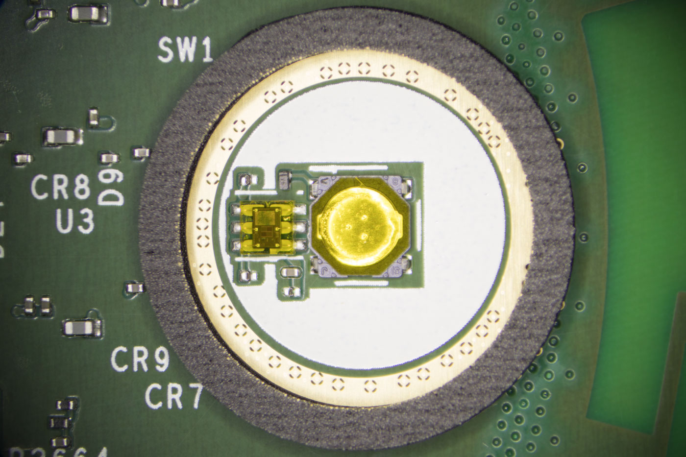
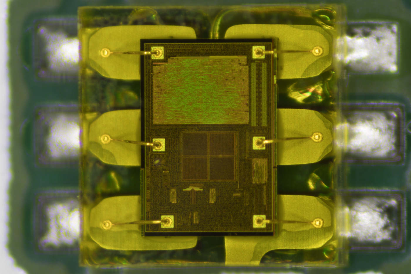
Light Sensor
ADC
Microphone
USB Input
eMMC to SD Card Wiring


Jeremy
It looks like there are twice as many DAT lines on the bga as there are on the sd adapter. Am I missing something?
Richard Green
your point being?
Dubbie
You can generally talk to eMMc men with 4 wires or 8. It just takes twice as long with 4
Earl
I got three on Black Friday, two for me and one as a gift. I just tore one of mine apart, since that's what I got if for and saw all the shielding. I almost tried to remove it to see what was under it and decided to see if someone had done it for me. Looks like a couple days earlier and I would have been doing it myself and probably had the same fate as you.
Thank you for killing yours so I don't have to kill mine.
Ierlandfan
Great work! Can you make a picture of the PCB (Without the memory chip) so we can trace for testpoints? And can you share the content of the rootfs?
Brian
Ierlandfan, We have already tested all available pins and test points to see if its possible to access the data lines and there are none available.
I wont be sharing the content of the drive as I don't want any legal problems with Amazon
DM
Without the eMMC (or if the address pins are shorted) does the MTK bootrom show itself on the USB?
Brian
DM, This is what you get using lsusb when accessing it via USB without the eMMC connected:
Device: ID 0e8d:0003 MediaTek Inc. MT6227 phone
Couldn't open device, some information will be missing
Device Descriptor:
bLength 18
bDescriptorType 1
bcdUSB 1.10
bDeviceClass 2 Communications
bDeviceSubClass 0
bDeviceProtocol 0
bMaxPacketSize0 64
idVendor 0x0e8d MediaTek Inc.
idProduct 0x0003 MT6227 phone
bcdDevice 1.00
iManufacturer 0
iProduct 0
iSerial 0
bNumConfigurations 1
Configuration Descriptor:
bLength 9
bDescriptorType 2
wTotalLength 67
bNumInterfaces 2
bConfigurationValue 1
iConfiguration 0
bmAttributes 0x80
(Bus Powered)
MaxPower 0mA
Interface Descriptor:
bLength 9
bDescriptorType 4
bInterfaceNumber 0
bAlternateSetting 0
bNumEndpoints 1
bInterfaceClass 2 Communications
bInterfaceSubClass 2 Abstract (modem)
bInterfaceProtocol 1 AT-commands (v.25ter)
iInterface 1
CDC Header:
bcdCDC 1.10
CDC ACM:
bmCapabilities 0x0f
connection notifications
sends break
line coding and serial state
get/set/clear comm features
CDC Union:
bMasterInterface 0
bSlaveInterface 1
CDC Call Management:
bmCapabilities 0x03
call management
use DataInterface
bDataInterface 1
Endpoint Descriptor:
bLength 7
bDescriptorType 5
bEndpointAddress 0x84 EP 4 IN
bmAttributes 3
Transfer Type Interrupt
Synch Type None
Usage Type Data
wMaxPacketSize 0x0040 1x 64 bytes
bInterval 1
Interface Descriptor:
bLength 9
bDescriptorType 4
bInterfaceNumber 1
bAlternateSetting 0
bNumEndpoints 2
bInterfaceClass 10 CDC Data
bInterfaceSubClass 0 Unused
bInterfaceProtocol 0
iInterface 2
Endpoint Descriptor:
bLength 7
bDescriptorType 5
bEndpointAddress 0x81 EP 1 IN
bmAttributes 2
Transfer Type Bulk
Synch Type None
Usage Type Data
wMaxPacketSize 0x0040 1x 64 bytes
bInterval 0
Endpoint Descriptor:
bLength 7
bDescriptorType 5
bEndpointAddress 0x01 EP 1 OUT
bmAttributes 2
Transfer Type Bulk
Synch Type None
Usage Type Data
wMaxPacketSize 0x0040 1x 64 bytes
bInterval 0
Ierlandfan
Hi Brian, thank you for the previous answers, I didn't knew it was you who was featured on Hackaday a few months ago! You tried to make a scatter file back then. Did you succeed in creating one since you have more info of the inners of this device? Or are you planning to solder in a SD card where the eMMC used to be?
Brian
Ierlandfan, we haven't got any further with the scatter file. We are looking into using an SD card but they only use 4 data lines and the emmc interface appears to use all 8 so it may not work.
DM
Are there "easily" accessible testpoints for the I2C - SDA and SCL?
What would be the obstacles to using this whole device just for its audio hardware by running the I2C to a more open SBC?
Brian
DM, we haven't found any accessible I2C points on the board
Marc
Great work wow! I wanted to see a teardown of the Input! You gave lots more than that!!!
setupecho
Thanks for sharing this article.
Ferran
What are the features of the DAC ?