We have previously torn down several Amazon Echo devices, including the 3rd gen Dot, 3rd gen Dot with Clock, the Flex, the Echo Input, and the Echo Dot 4th Generation. In this teardown, we will look at the new Echo Dot 5th generation model, a smart speaker with the Amazon Alexa service.
The 5th generation Echo Dot is a new model announced in September 2022; the new design has the same round appearance and buttons on the side of the curved section as the previous version 4 device.
New with the 5th Generation includes an Improved audio experience for clearer vocals, deeper bass, vibrant sound, a built-in temperature sensor, and eero wireless technology, which is Amazon's whole-home WiFi coverage system using a mesh network.
Amazon Echo Dot 5th generation vs Echo Dot 4th Generation
- Dot 5 and Dot 4 are the same physical size at 100 x 100 x 89mm.
- Dot 5 no longer has the audio port on the device's rear.
- Dot 5 has a new larger speaker measuring 1.73 inches compared to 1.6 inches on the Dot 4 model.
- Dot 5 has a new temperature sensor.
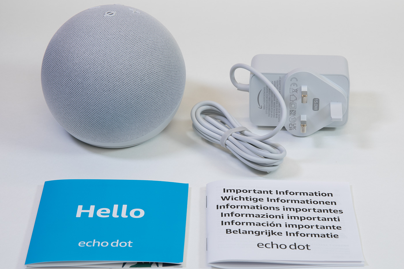
In the Box
- The Echo Dot
- 240V UK power supply
- Setup instructions
- Echo Dot terms of use
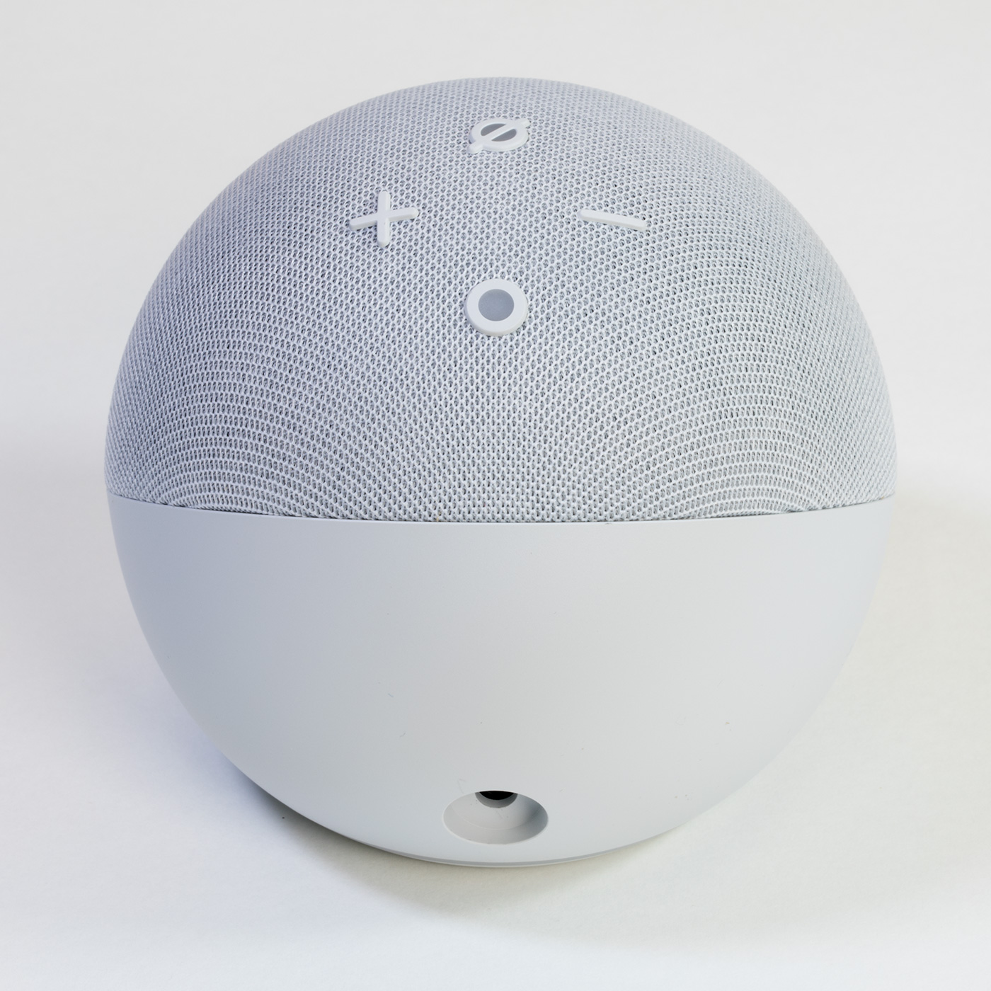
Top of the Echo Dot
The top of the smart speaker has four buttons. The + and – buttons control the volume; the circle button activates Alexa, and the circle with a line through it enables or disables the microphones.
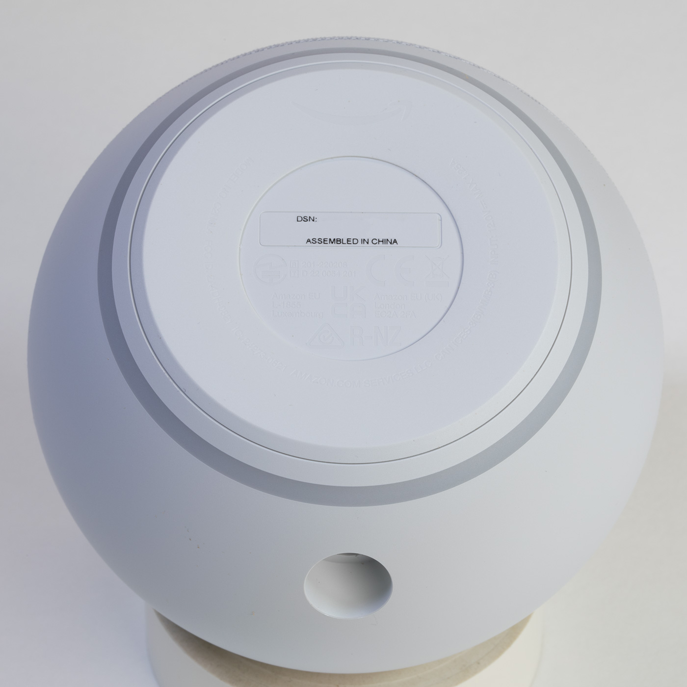
Case Base
The base has the serial number, product logos, and certification marks.
On the rear, a power input socket. The previous version had a headphone/audio out 3.5mm stereo socket, but it has been removed for the 5th generation model.
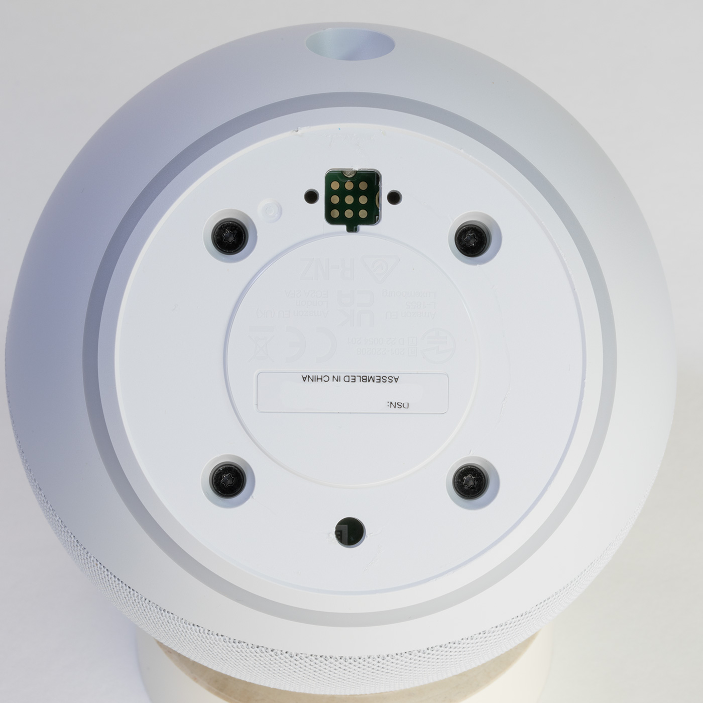
Opening the Case
The cover is held in place using adhesive tape and locator pins.
To open the case, first, you need to remove the non-slip rubber cover on the base of the echo dot using a thin knife or some other flat-bladed tool.
Under the cover, you will find four T5 Torx bolts and a recessed nine-pin header which appears to be a debug or programming port.
Removing the four T5 Torx bolts allows you to separate the two halves of the case.
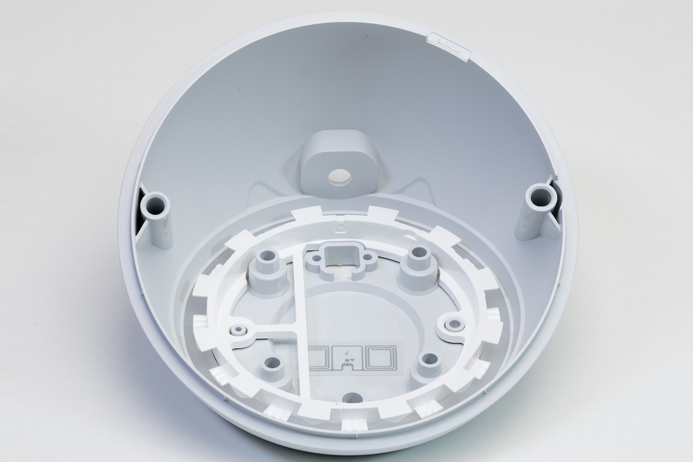
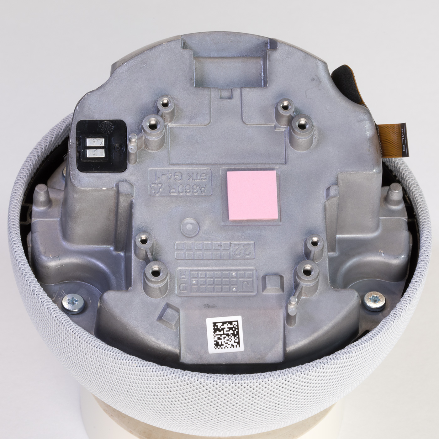
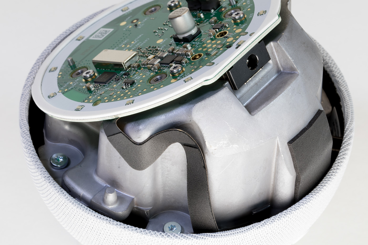
Metal Chassis with Processor PCB
Inside you will find a circuit board mounted to a cast metal housing with a small ribbon cable leading to the switch PCB.
The PCB is removed using four Torx bolts and the removal of a small flat-flex cable.
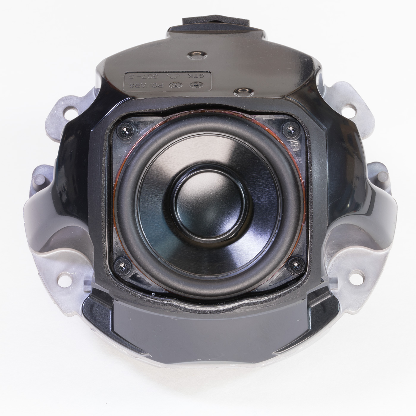
With the PCB removed, the four silver Torx screws can be removed, allowing the metal housing to be removed from the top cover. This reveals the switch PCB and speaker.
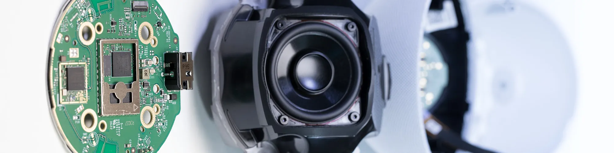
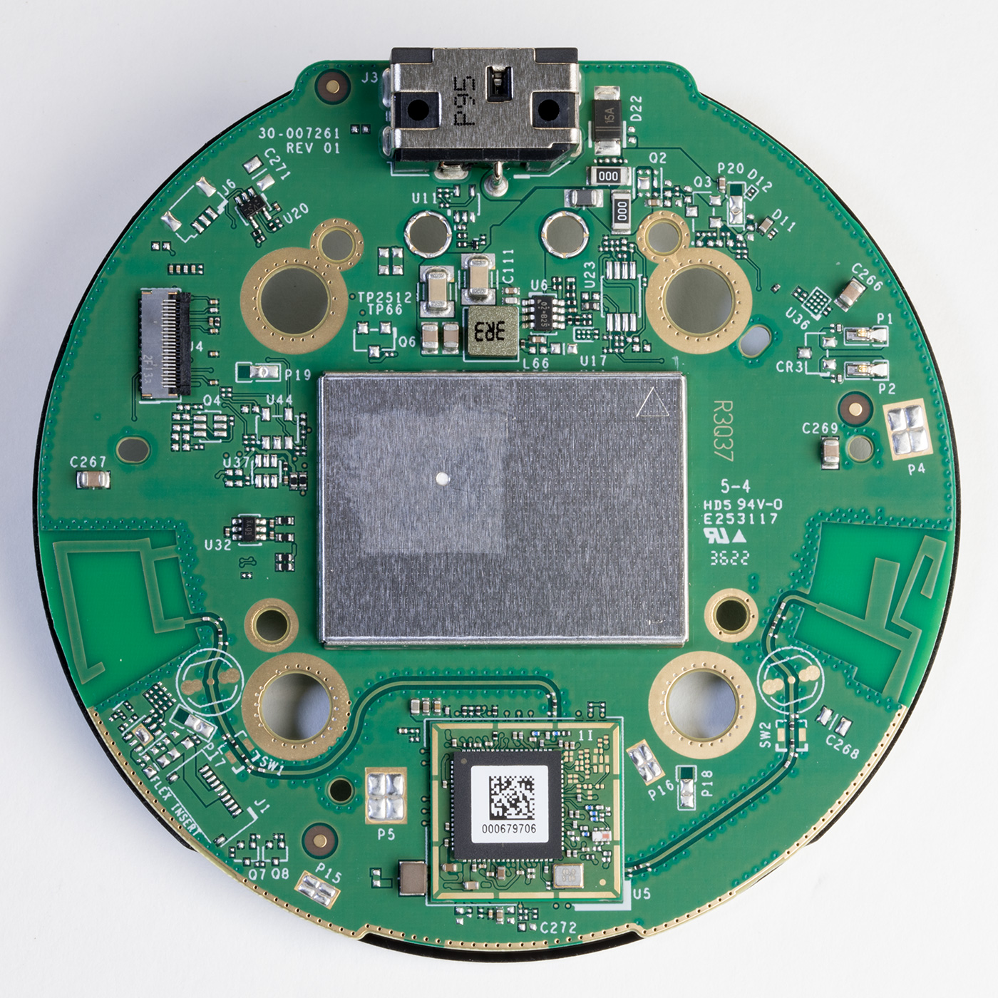
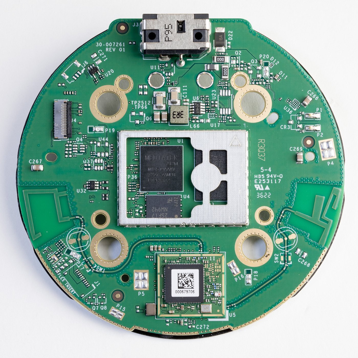
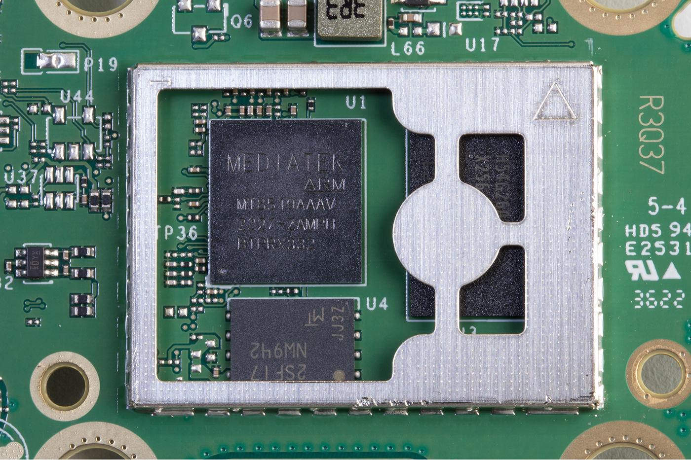
The upper side of the Processor PCB
Revision 5 of the Echo Dot uses an AZ2 processor, an updated version of the Amazon Neural Edge processor. The new processor is marked as MT8519BAAV, but I have not found any public information about this processor. Storage is provided with a Micron NW942 Nand flash IC. RAM is provided with an SK Hynix H54926AY 0.5GB model with a speed of 4266Mbps located under a metal shield.
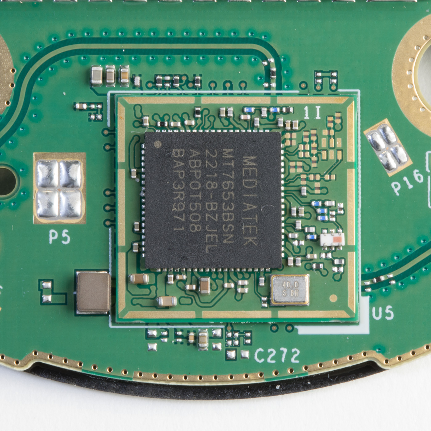
Below the CPU and Ram is a MediaTek WiFi / Bluetooth Controller, part number MT7653BSN which outputs two PCB antennas, one on each side of the board. This is now mounted on a smaller daughterboard PCB compared to the direct central PCB mounting on previous versions.
Above the metal shield is the power socket.
A single flat flex connector links the processor PCB with the top switching and microphone PCB.
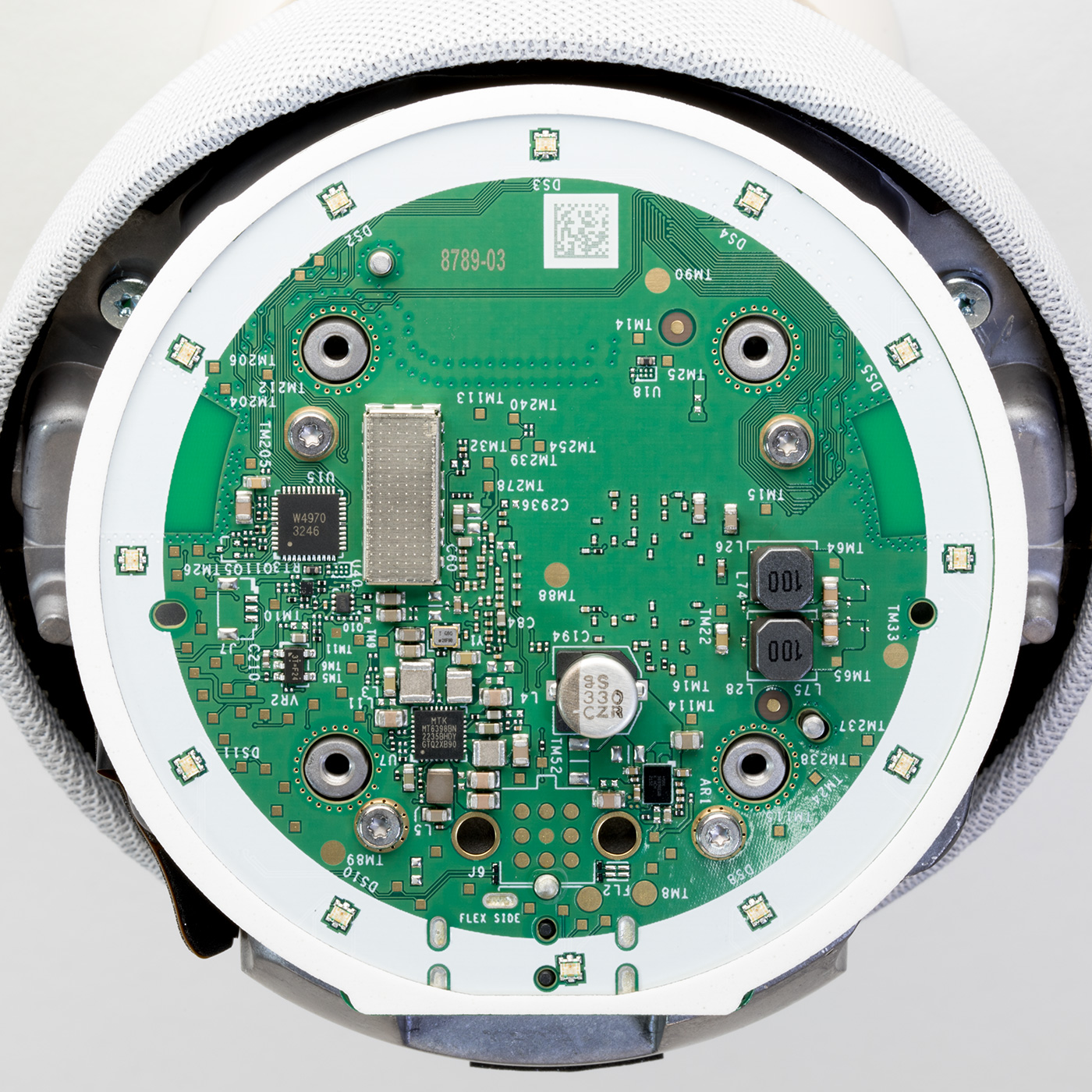
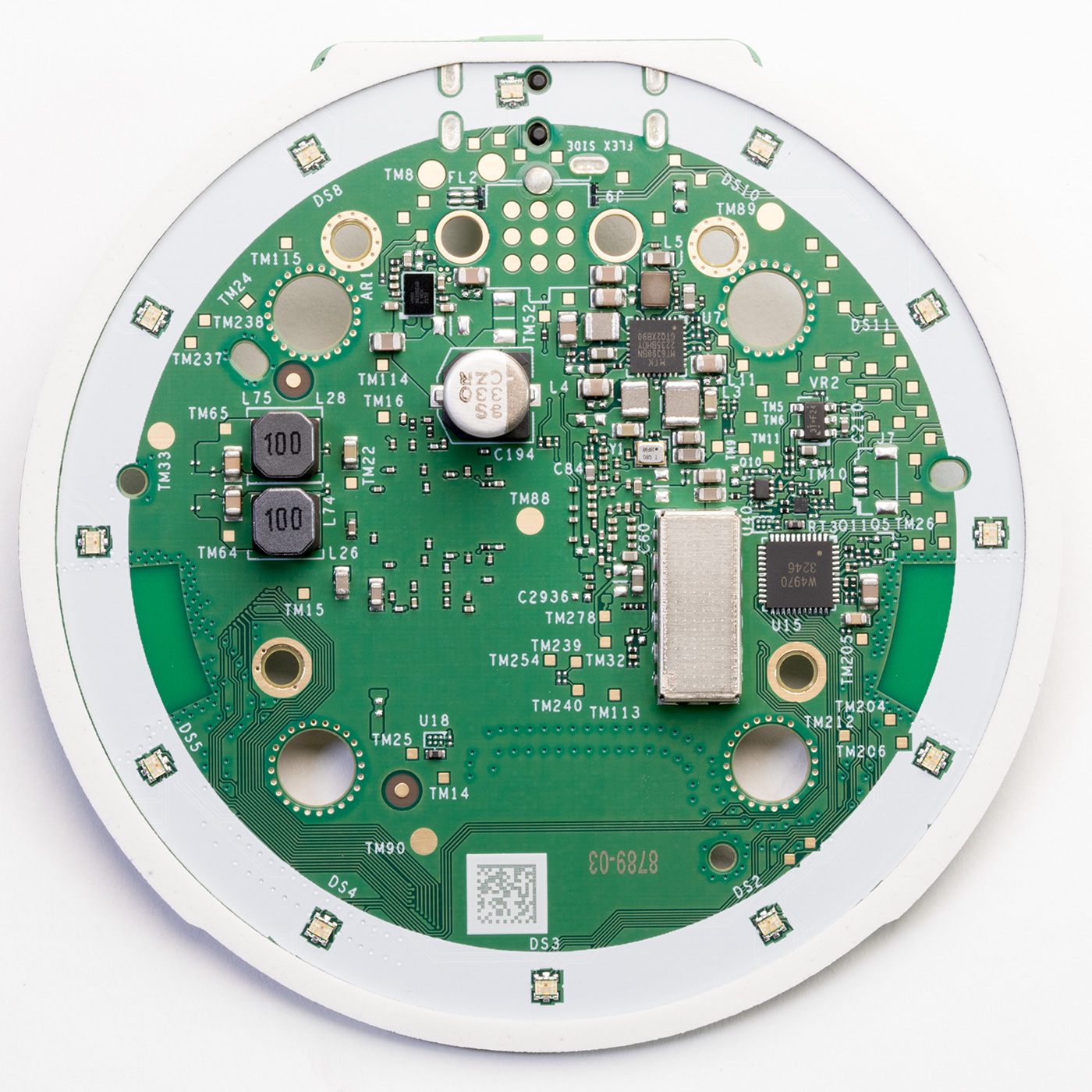
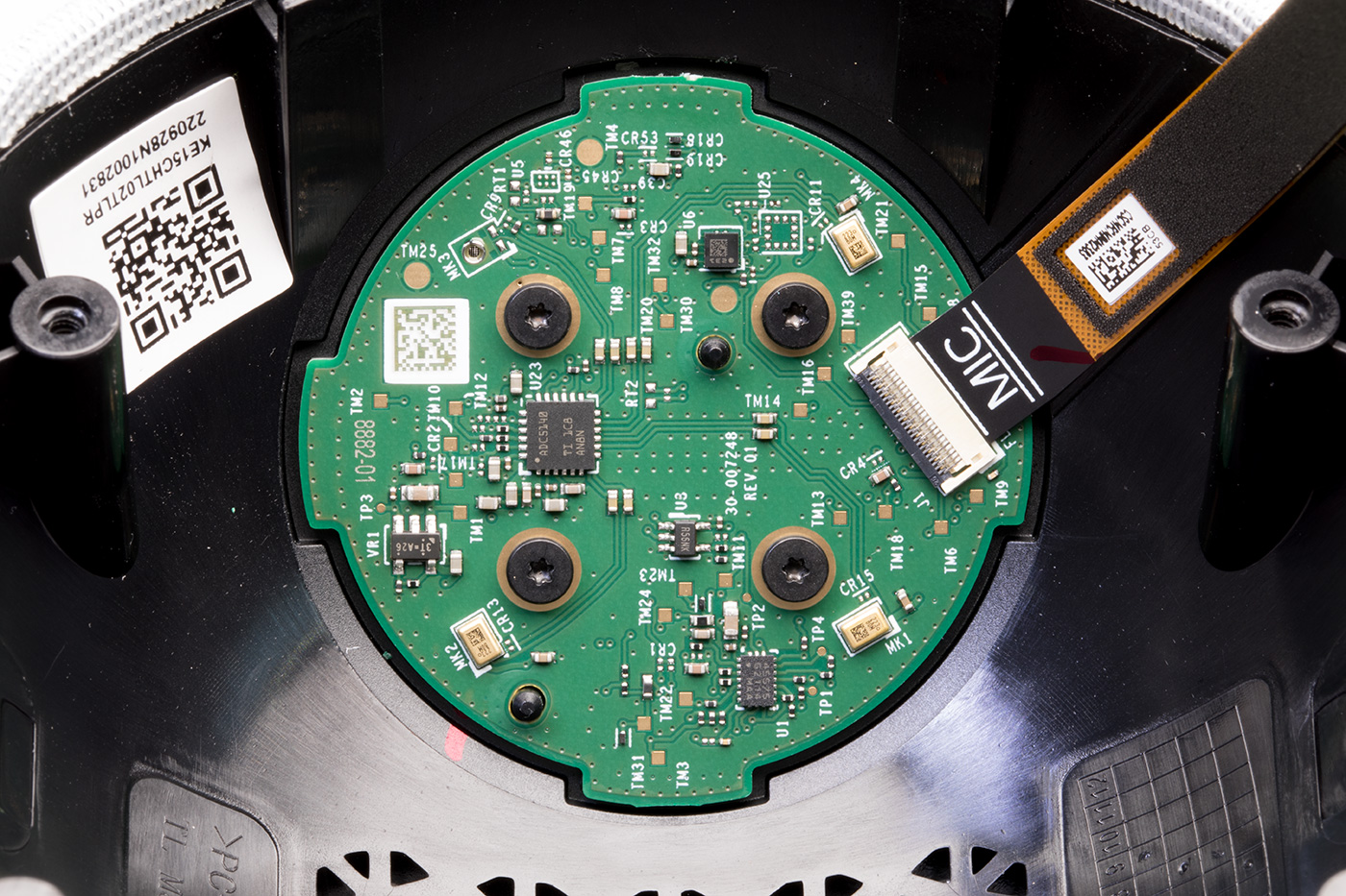
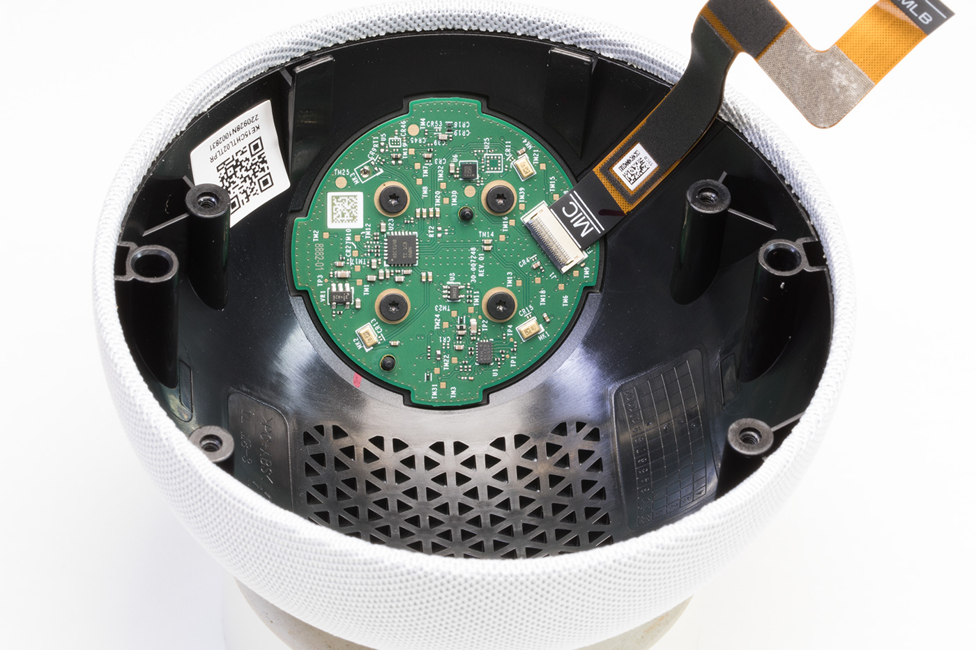
The lower side of the Processor PCB
On the lower side of the main PCB are 12 RGB LEDs around the edge which a W4970 3246 RGB LED driver drives.
The internal speaker is driven by a Maxim integrated MAX98396EWB Digital Input Class-DG Amplifier with an output power of 20W into 8 ohms or 19W into 4 ohms.
There is a chip marked MT6398BN, which is an unknown MediaTek part but based on the surrounding components, it appears to be a switching power supply.
There is a small metal enclosure soldered into the PCB; we did not want to risk damaging the board by removing this.
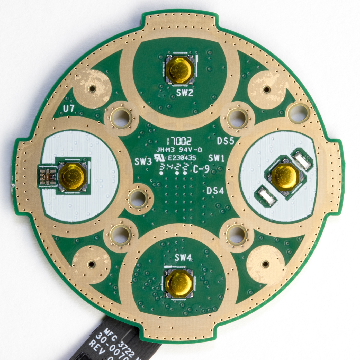
Upper Switch PCB
The small round PCB, which is screwed into the top of the case, contains four buttons, two LEDs, and a light sensor on the upper side with a soft rubber gasket.
This is fixed into the upper case with four small bolts and strong glue.
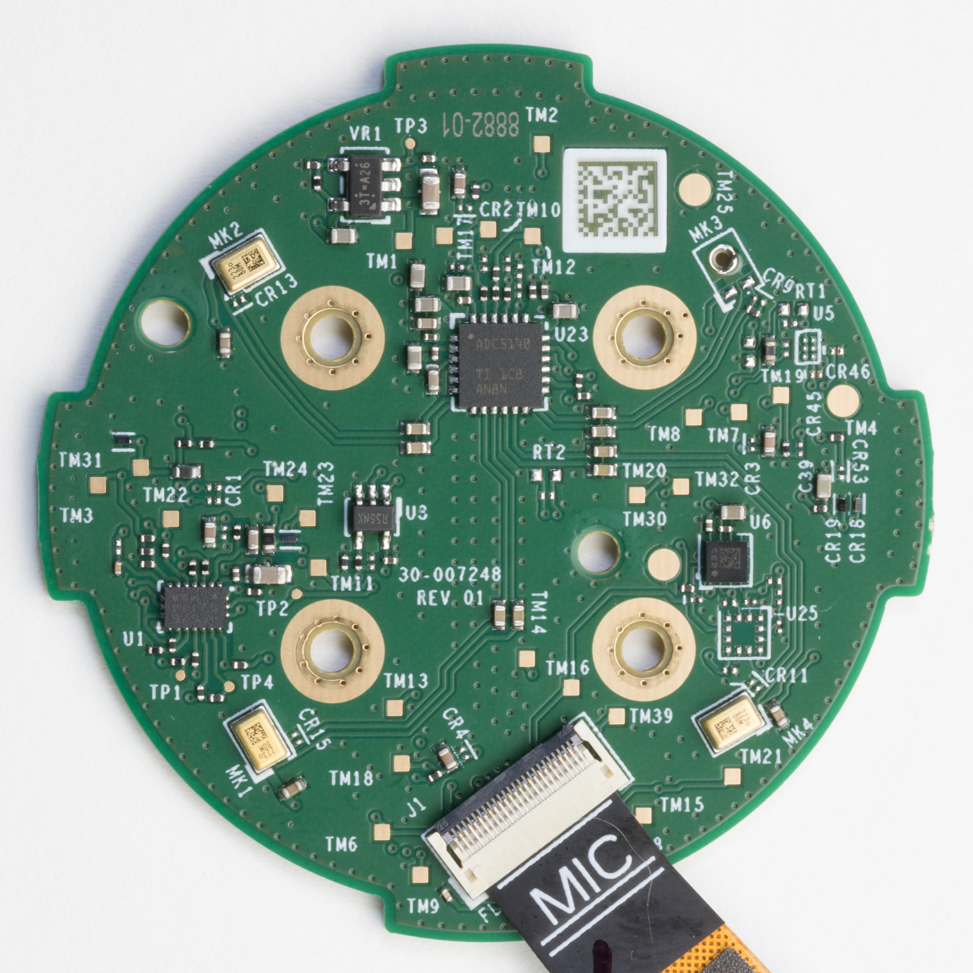
On the reverse of the circuit board are three microphones and a TLV320ADC5140 Texas Instruments Quad-channel 768-kHz Burr-Brown™ audio analogue to digital converter. There are several other smaller ICs on the board, but we could not find any information on what they are.
The Echo dot uses the three microphones to locate the direction the voice is coming from and filter out background noise. There is a space for a fourth microphone like on previous versions, but the pads were unpopulated on our device.
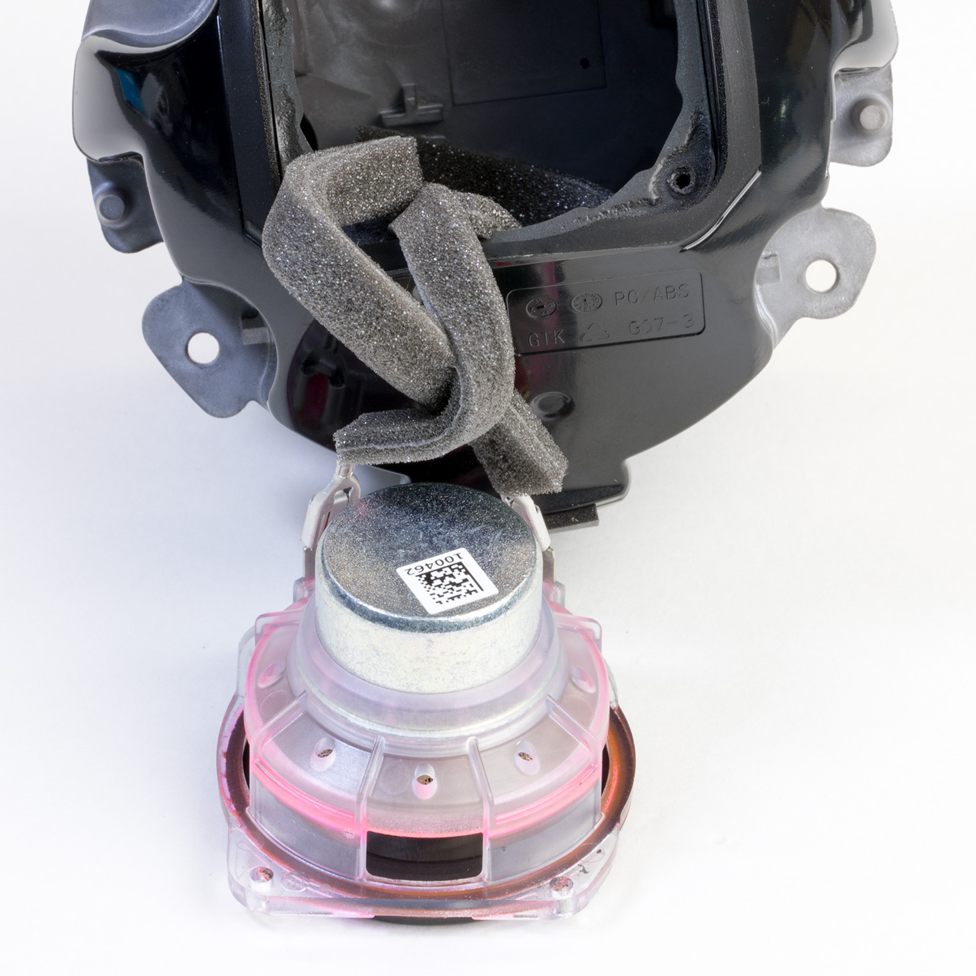
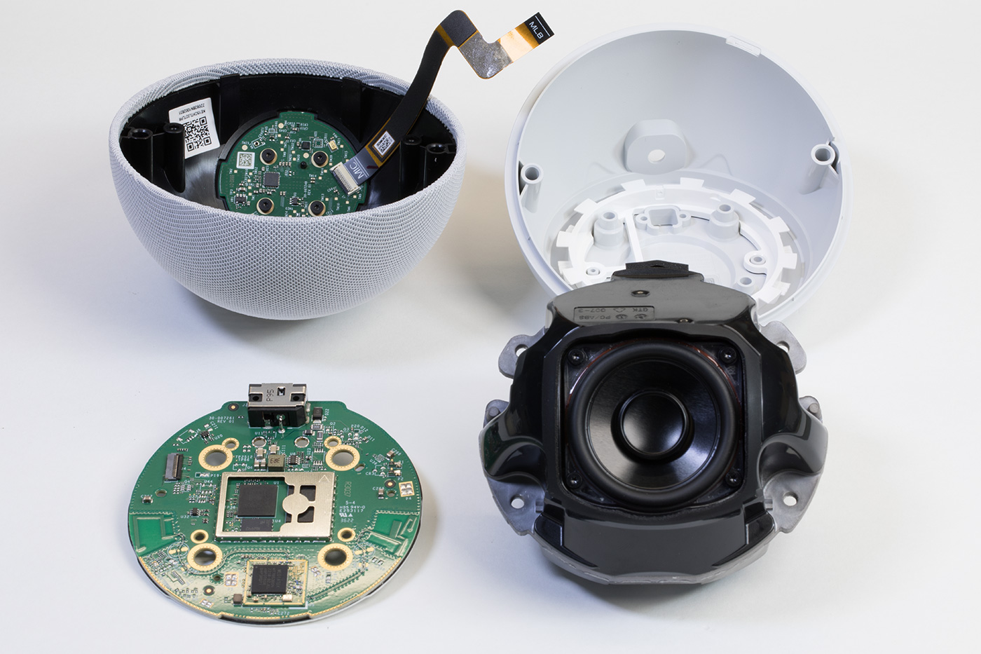
All internal parts
All the internal parts that make up the echo dot.
Power Consumption
We measured the power consumption of the Amazon Echo Dot 5 with a Hopi mains power meter.
| Device Status | Power in Watts |
|---|---|
| Booting the device | 1.8W |
| Idle waiting for input | 1.3W |
| Responding to a user command | 1.5W |
| Medium volume with music playing | 2.4W |
| Maximum volume with music playing | 3.9W |


Boris
From the general info here and there, the new SoC should be AZ2. :)
Boris
Btw I'm watching now closely the photos. You wrote multiple times in the review, that it's using MT8512BAAV (which is the original AZ1), but when I zoom, I see MT8519BAAV - aka "19" vs "12". So definitely it's the AZ2.
Brian
Thank you for spotting the mistake in the post. The part number has now been updated.
Cannonfoddr
Is there any difference between the 5th gen Dot cct board that has a display & this one without?
Are they using same board but have a display/ daughter board fitted to allow display to save costs? If so could a non-display dot be modified to have a display added
Blu5
@Cannonfoddr: based on this great teardown, I bought an Echo Dot 5 with a Display and made my own Teardown with further part identification. (I’m starting a bigger open source project based on echo dot devices)
The base board is equal but has some more ICs, Rs and Cs. I also think that you can‘t clone the LED/display board without a lot of money. Better spend some €/$/£ to buy a Dot with display.
Another point is the different firmware, which has to be flashed.
So in conclusion: theoretically you can convert a non-display dot, but it's not worth the effort.
EchoUser
@Blu5, I have a 2nd and 3rd gen echo dot. I was able to modify the 2nd gen echo dot's preloader and lk and am able to run custom image on it.
If you can share the detail of your opensource project, I will love to join and contribute in the same
RCdT
With your teardown of the 4th gen you provided the wattage values (mono and stereo) for the amplifier chip. Can you provide this detail for this updated amp chip? Would it be possible to solder in a stereo line out somewhere or does this version only have a mono amplifier since it doesn't have an auxiliary audio port?
You mention three times that there is a temperature sensor but then do not show where it is among the hardware/components on the board. Where do you think it lives?
Brian
Hi RCdT,
I have added the audio amp output wattage from the datasheet on https://www.mouser.co.uk/datasheet/2/256/MAX98396-2449506.pdf to the post above. The datasheet does not mention being able to drive stereo headphones as it is a mono Class-DG speaker amplifier.
With regards to the temperature sensor, we have not been able to locate the chip responsible for this.
Diymariuselectro
tnx for teardown.now I use dot2 from usb car adapter,and powered from my solar batery soket,that gives me from 12.5v to 14.5 v.I want to conect my dot5 to solar batery soket,.My question is if u can put a colsed pic with supply part,so we can see if I can power this up frum 12.5 to 14.5 or I have to put a stabilizer to 12v.tnx
Brian
If you use a switching DC to DC regulator module it will be able to run from the 12.5 to 14.5 volt inputs.
Chris Card
Brilliant teardown, thank you for the good info. You mentioned the Mediatek MT6398BN assumed to be the switching power supply chip but I don’t find any info on this online, so I can’t check the maximum voltage this might support.
I have a similar application to Diymariuselectro who posted above. I’d like to run the echo dot from a battery which will have a range of 14.4V down to 12V depending on state of charge. I know the safe answer is add a buck / boost regulator module to fix the output voltage at 12.0 but I’m hoping you or someone else who reads this may have tested the generation 5 echo dot on a range of input voltages and might be able to confirm that yes it could tolerate up to 14.5V without damage. My guess is it will work, but I don’t want to be the one to find out that it doesn’t, so just thought I’d ask! 😂
Markus
Hello Brian,
at https://www.briandorey.com/post/echo-dot-3rd-gen-digging-deeperhast you developed and mentioned a debug adapter for the Echo Dot 3rd.
Have you possibly also developed such an adapter for the Echo Dot 5 and do you also sell it?
Background:
As the Echos are a disaster from a data protection point of view, but the hardware would be very attractive for our home automation with Home Assistant and the look is "suitable for women", I should try to "de-Amazonize" them.
Thank you very much for your efforts.
Brian
We have not made a debug adapter for the 5th gen echo dot but the pins on the NAND flash are exposed so it might be possible to solder wires directly onto the chip and dump the contents of the flash memory.
Dean
I'm trying to build this (https://www.hackster.io/tmburns/breathing-life-into-an-amazon-echo-device-ed9ea3) using a Gen 5. Do you have any idea where I can take the "wake" signal from the Gen 5?
Thanks!
Chris Card
Hi!
Checking back for replies to my previous comment, but I didn’t find any :). Well thank you for the awesome tear down article, which is really interesting to read.
Does anyone know, or able to test the range of inout voltages this Echo Dot will safely run from? I want to run mine direct from a LiFePO4 battery which would be 14.4V fully charged. Has anyone run this device from a battery without an external to regulator to fix a 12V inout voltage?
Brian
I havent tried running the device from different voltages. I might be a good idea to use buck-boost voltage converter to give you a stable 12v supply from the battery.
Cosmin
Hello.
My DOT is located under a shelf and the light sensor doesn't work.
Any ideas how cand i solve that?
I would try to relocate the sensor itself, but i don't think i can use the same sensor. What sensor can i use?
Fabio menezes
Onde compro o flex dos botões da echo Dot ?
Mateusz
Hey, i have bought an echo dot 5th gen, that has a certain defect that it can't connect with the wifi/my phone. My question here is, if it's possible to buy the MediaTek MT7653BSN component, and replace it with the old one, and could it possibly work? My other question is where i could get one, because i've done some research and i can't find no site to buy one.
Kind Regards
layth
Hello, I have an Eco.dot device, 5G, and I have a mute issue. Can you help me solve the problem? Is it a major malfunction in the device?
amphack
anyone managed to get the firmware?