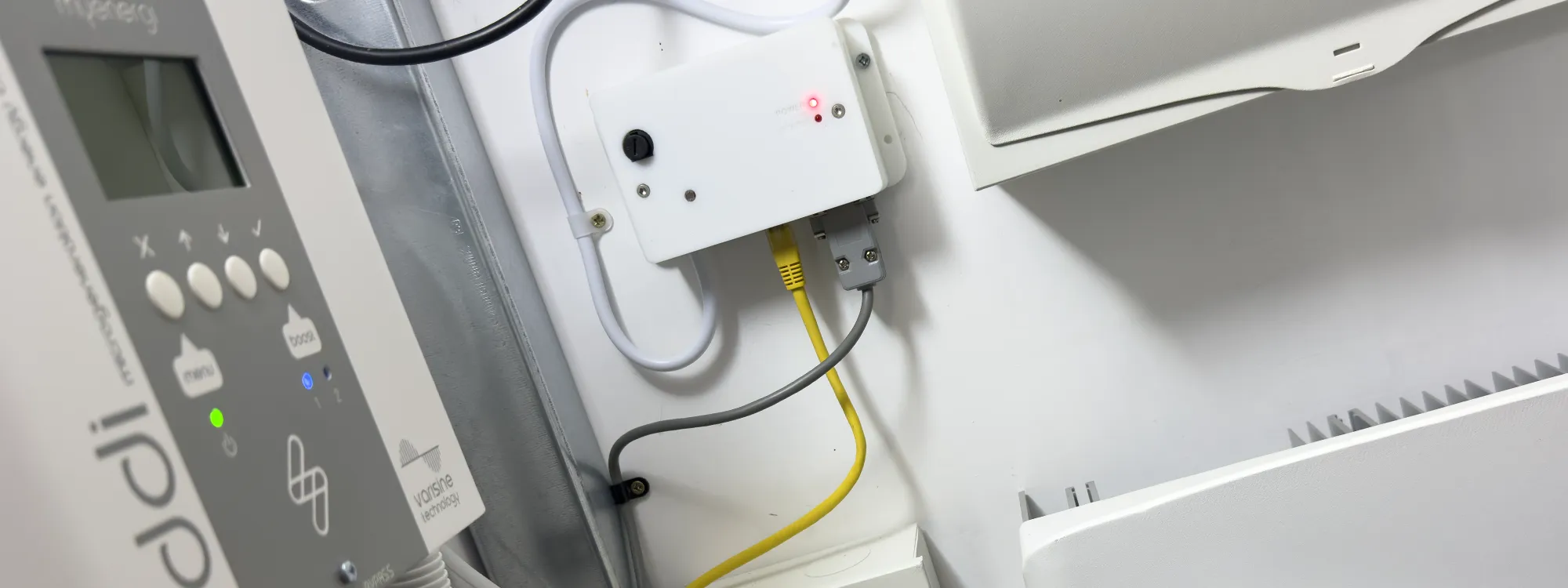
Our home solar installation uses a Solis 1.5kW Solar PV Inverter to connect the solar panels to the mains supply. The inverter came with a Wi-Fi interface to monitor the PV generation. It was designed to connect to the Solis cloud service in China and could not be accessed locally. As we prefer to keep our data local, preferably within the house or at least on the same continent, another solution was required to connect to the inverter.
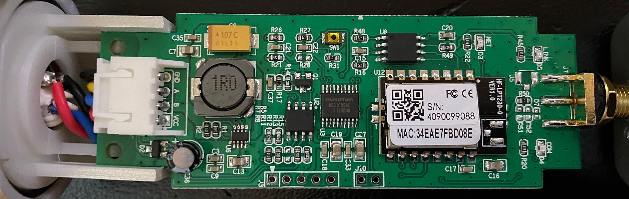
The inverter has a RS-485 interface, so we initially used a Raspberry Pi with a RS485 Pi interface to connect to the inverter. This worked well and allowed us to send the data to Home Assistant using a MQTT broker. The downside of using a Raspberry Pi was the power consumption. We try to keep our energy consumption as low as possible. Using a Linux computer just to send a few bytes of data to a MQTT broker seemed like overkill. While the Raspberry Pi is slow compared to modern desktop computers, it is still far more than was necessary, so we looked for another option.
ESP32 based RS485 to MQTT bridge
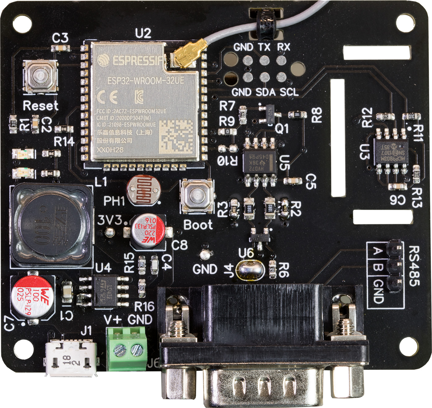
The replacement for the Raspberry Pi was an ESP32-based RS485 to MQTT bridge. This used less power than the Raspberry Pi and put the ESP32 processor, RS485 transceiver and a temperature sensor all onto a single PCB.
We installed the ESP32-based bridge in October 2022, and it has been there for nearly four years copying data from the inverter to our MQTT broker. After installing the new bridge and running it for several months, we found that it had a few problems. The ESP32 bridge used Wi-Fi instead of Ethernet to connect to our network. We have used the same method with other ESP32 devices around the house and never had any issues. The ESP32 bridge however, would lose connection to the Wi-Fi router and crash, needing a full power cycle to get it running again.
Wi-Fi connection problems
The solar inverter and ESP32 bridge are in our shed, located beneath the back of the house. Because the house has thick concrete floors, there's over 2 metres of solid stone and concrete between the bridge and the Wi-Fi router.
Wi-Fi signals do not easily pass through stone and concrete, so the signal was very weak. We would sometimes get several weeks between needing to restart the bridge, but other times it would need to be restarted every day.
After updating the firmware several times to make it more reliable, we ended up using a time switch on the power supply to cycle the power twice a day. This worked reasonably well and fixed the issue for a while.
Over the past few months, we found that the bridge would stop working several times a day and needed to be manually restarted. This could be due to more noise from an increasing number of Wi-Fi devices in the area. We live in a street of terrace houses, so there are lots of other Wi-Fi routers and Wi-Fi-connected devices nearby. We needed a new solution that did not rely on Wi-Fi while keeping energy consumption as low as possible.
Designing a RS485 to Ethernet bridge
We looked at several options for the new Ethernet bridge before deciding to build something around the Arduino software framework.
The microprocessor that we chose is the Microchip/Atmel ATmega32U4. This is the same chip used in the Arduino Leonardo, so we could use the bootloader and libraries for the Leonardo in our circuit. The ATmega32U4 has the advantage that it has a built-in USB port so you can reprogram the board directly through a USB port instead of needing an IDC programmer. At least that was the original plan, but as we found out later, that would not be possible.
The RS485 interface is built around a Texas Instruments SN65HVD72D, which is the same chip we use in our RS485 Pi board. The circuit for the RS485 interface is the same as on the RS485 Pi, with the protection diodes and resistor. The only change was the addition of two 348R resistors used to pull the two inputs to 3.3V and ground. This is something we found was required in the earlier bridge circuits as the RS485 interface on the inverter does not bias the two data wires. A three pin header for the RS485 bus was added along side the DB-9 connector to use during development.
For the Ethernet interface, we originally planned to build an Ethernet circuit around the WIZnet W5500 Ethernet controller, using the circuit from their datasheet. While looking at how they work and trying to find a supplier for the W5500, we found a ready-made Ethernet to SPI module based on the W5500. It included the Ethernet control circuit on a small PCB under the RJ45 socket. This significantly decreased the number of components that would be needed on the board, so we decided to use one of these modules.
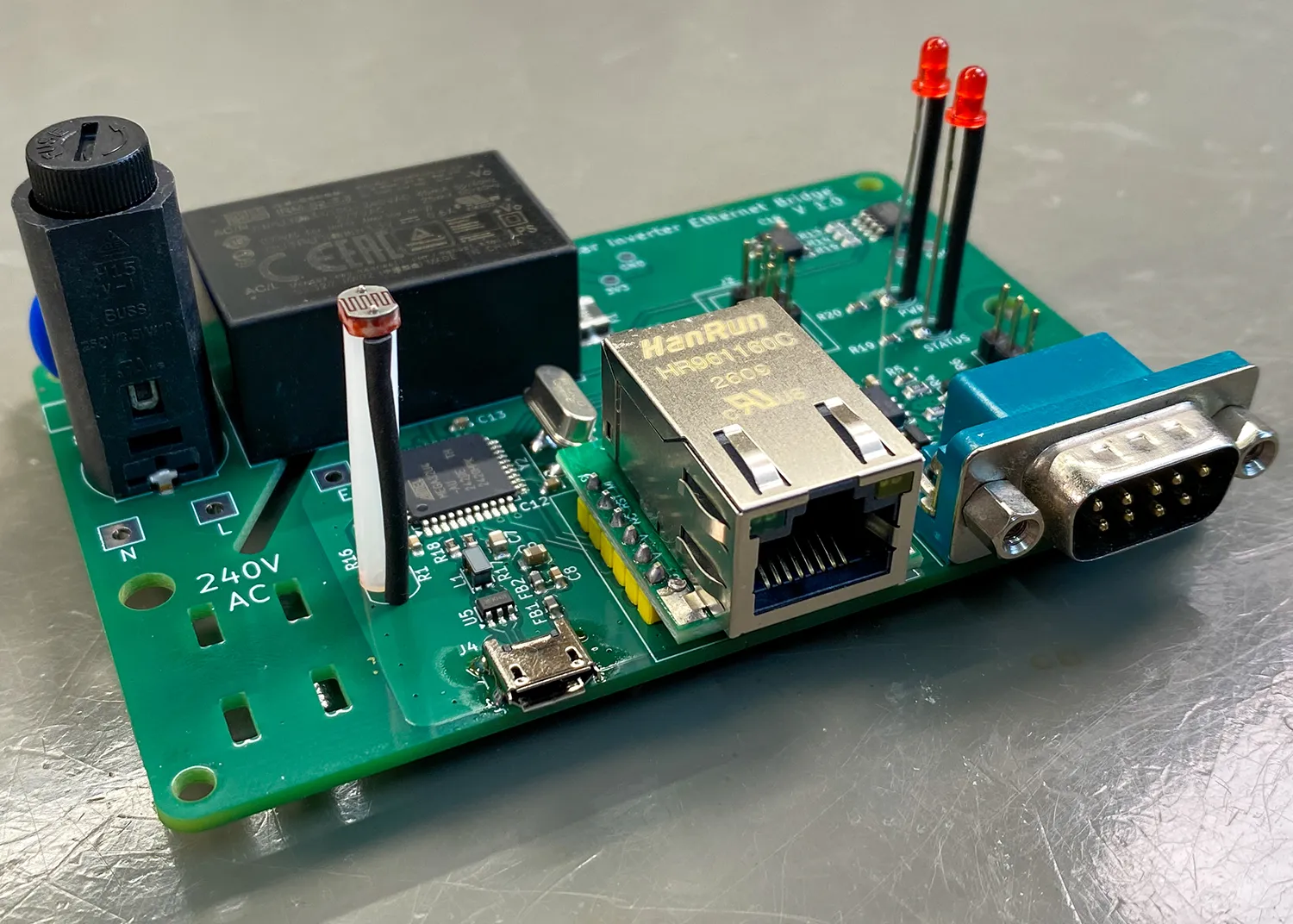
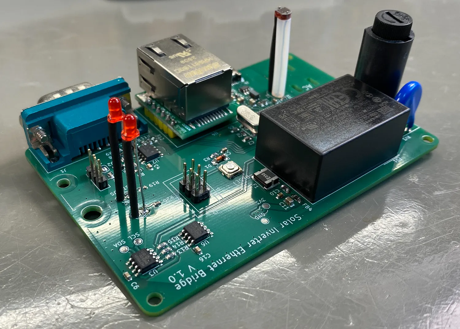
The previous Wi-Fi bridge included temperature and light sensors. We have temperature sensors in every room of our house, so including the temperature sensor on this board allows us to monitor the shed temperature. We use ZigBee sensors in the rest of the house, but with so many problems with Wi-Fi, a lower-powered ZigBee sensor in the shed was not an option.
We used the same Microchip MCP9803 I2C temperature sensors as on the previous Wi-Fi bridge. The photo resistor connected as part of a voltage divider on an ADC input to monitor light levels.
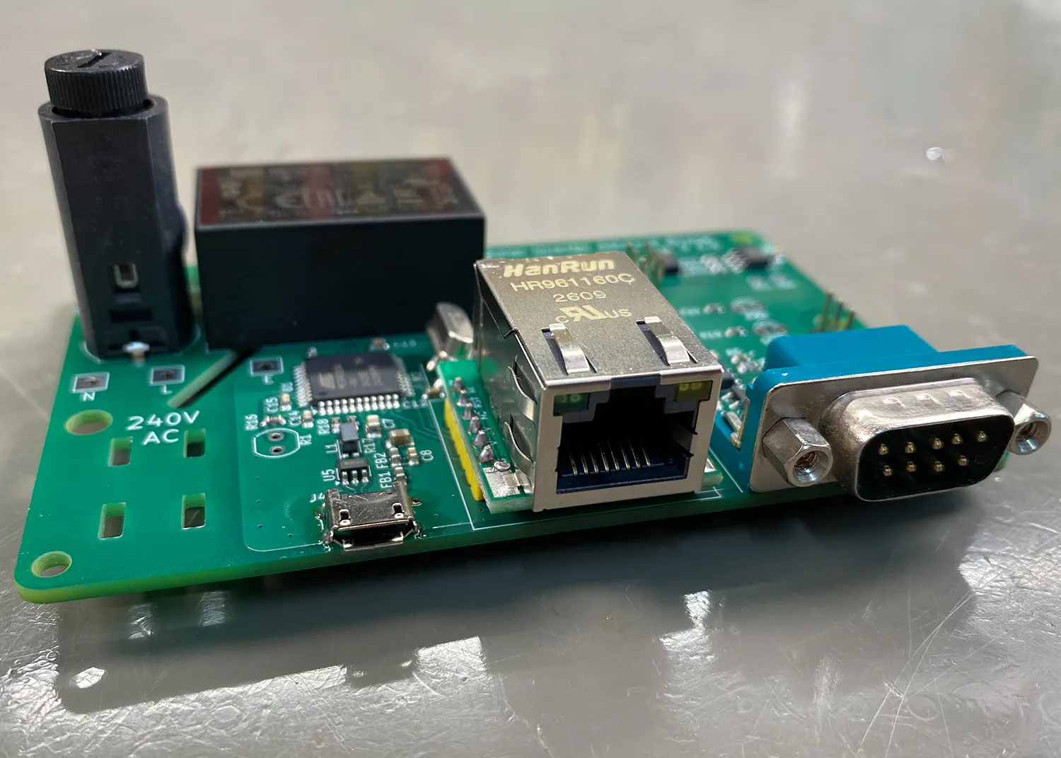
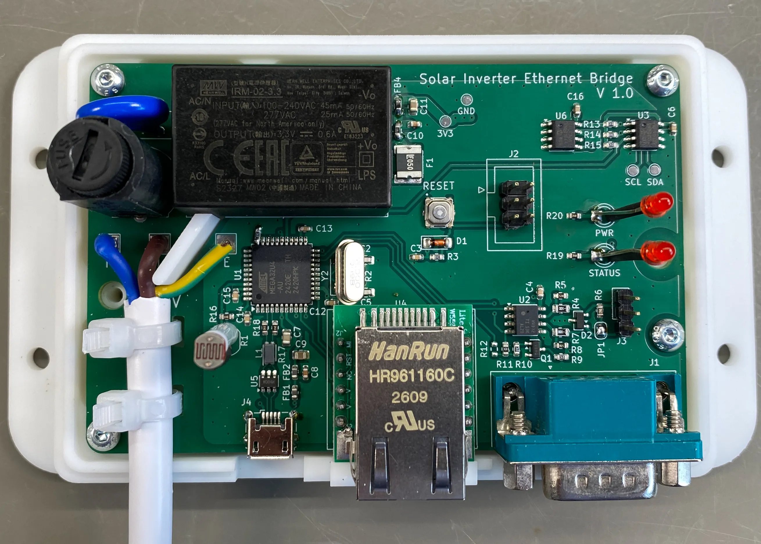
The light sensor allows us to check if the shed light has been left on, which has been known to happen in the past.
The previous Wi-Fi bridge was powered using a 5V phone charger. For the new design, we wanted it to be self-contained and powered from the AC mains. We found a 3.3V 2W isolated PCB-mounted power supply from Meanwell, part number IRM-02-3.3. This was used in the circuit with a fuse and surge-protecting MOV on the 240V AC input. A poly-fuse and filter circuit was added to the 3.3V output to reduce EMF interference.
The circuit around the ATmega32U4 was copied from the Arduino Leonardo schematic, with the addition of some extra filtering and over-voltage protection on the USB port.
The original plan was to use the USB port for programming the firmware as well as monitoring the output from the inverter, but after building the circuit we could not get the USB port to work. As far as we can see, apart from the extra filtering, the USB circuit is the same as the Arduino Leonardo. We spent several days trying to get USB to work before giving up and abandoning the USB port, using the ICSP port for firmware upgrades instead.
The ATmega32U4 has 32K of flash memory and 1K of EEPROM space, so a Microchip 24LC32 32K I2C EEPROM was added into the circuit to use as a data storage area. At the moment, the firmware is not using the additional EEPROM space, but it is there for any future upgrades.
The PCB
With the components selected, the circuit was laid out in the schematic editor in KiCad and a PCB was designed. The PCB layout puts the power supply on the top left of the PCB with an isolation slot between the high voltage and low voltage parts of the circuit. The slot was made big enough so a plastic shield could be built into the enclosure, adding an extra layer of isolation. Slots were also added into the PCB so cable ties could be used to hold the mains cable in place. A vertical fuse holder was used for the mains fuse, allowing the fuse to be changed without needing to open the enclosure.
The USB, Ethernet, and DB-9 RS-485 ports were located along the bottom edge of the PCB allowing all of the cables to exit on the same side.
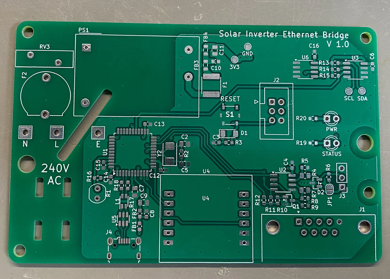
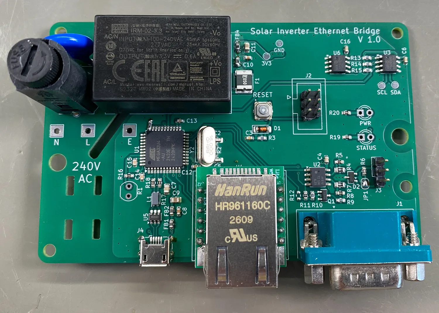
The temperature sensor was placed in the top-right corner away from the other components to reduce internal heating from affecting the sensor readings.
The microcontroller was placed above the USB port to reduce the trace lengths for the USB and SPI buses. The correct trace widths were calculated for the USB traces based in the four layer board stack-up that we used from JLC PCB. Care was taken to ensure all of the data traces on the USB, SPI and RS485 buses were the same length.
The Enclosure
Finding a ready-made enclosure would be difficult, so we decided to design one that could be 3D-printed. The enclosure is made in two parts.
The base has mounting holes for the PCB and four holes on the outer edge allowing it to be screwed to a flat surface. A raised plastic shield was added that comes up through the PCB under and along side the power supply. This gives better isolation between the high voltage components and the rest of the circuit.
The top of the enclosure was designed to fit over the base with a raised location strip around the edge. Two M3 bolts hold the two halves of the case together. Cutouts were placed in the lower edge for the three connectors and power cable. There are holes in the top for the fuse holder, two status LEDs and the photo resistor.
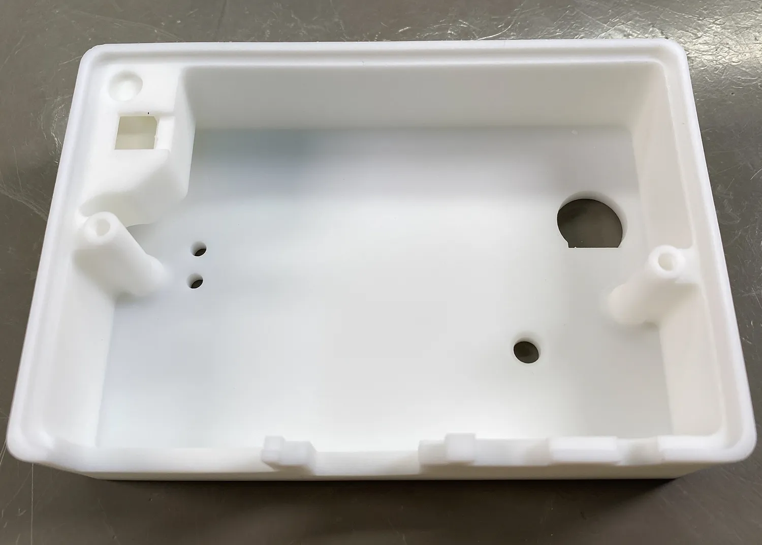
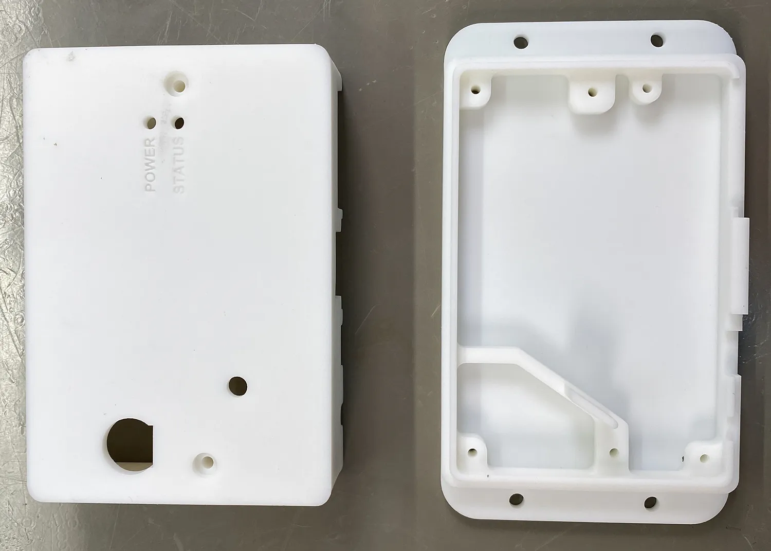
For the temperature sensor, we wanted it to have external access to the air in the shed. The case was designed with a tunnel that funnels air in from the side of the case, past the temperature sensor and out through the top. The case pushes down against the PCB around the sensor, isolating it from the internal air in the case. Hopefully this will help it give a more accurate reading for the shed temperature. With the PCB and the enclosure designed, both parts were ordered from JLC PCB, along with a paste stencil for the PCB. The total cost of the PCB, stencil and two enclosure parts was £37.17 including shipping and import fees.
We already had most of the components in stock in the workshop. The only parts we had to buy for the project were the power supply and Ethernet module. The ATmega32U4 was kindly sent from Microchip as a free sample.
Assembly
A few weeks later, the PCB and enclosure arrived. The PCB was pasted with solder paste, and all of the SMD components were placed on the board. The PCB was then cooked in our reflow oven, soldering all of the SMD components into place.
The next step was to solder all of the connectors and through hole components onto the board. The photo resistor and status LEDs needed their legs extending so they would reach the front of the enclosure. Heat shrink sleeving was used to stop their leads from shorting out.
As with any project, there were a few issues that had to be addressed during development. The design used a 16MHz crystal and during assembly I grabbed what was labelled in my collection as a 16MHz crystal, only to find out later that it was 8MHz. Unfortunately, I did not have any surface mount 16MHz crystals in stock so to save on time and postage costs, I soldered a metal can through hole crystal to the board instead.
The Firmware
The firmware was based on the ESP32 firmware using in the Wi-Fi bridge, with changes made to make it work with the ATmega32U4 microcontroller and the W5500 Ethernet controller. We used Microchips MPLAB IDE for development, with the help of Claude AI to convert some of the code to the new Atmel architecture.
The firmware starts by initialising all of the hardware and then sits in a loop reading data from the solar inverter. The inverter data, temperature sensor and light sensor are sent to the MQTT broker at regular intervals.
Downloads
You can download a copy of the firmware, case and PCB files on our GitHub repository at github.com/briandorey/solis-inverter-ethernet-bridge.
Testing
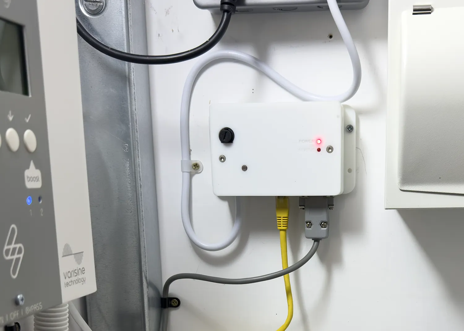
After writing the new firmware and programming the board, we found problems with the USB bus. Several attempts were made to get it working, but in the end that part of the project was scrapped.
All of the other parts of the circuit worked as expected. During firmware development, we used a Raspberry Pi with a RS485 Pi and a Python script to emulate the solar inverter. The Ethernet bridge read the values from the inverter emulator, along with the temperature and light level and sent them to our MQTT broker. We ran it for several hours to test its stability before connecting it to the real inverter. So far it has been running for two months without any freezes or needing to be power cycled.
We may add a surge protector on the Ethernet port in the future. The RS485 port has surge protection, but a previous lightning strike on an antenna connected to a computer took out our entire computer network through the Ethernet cable. We are now more cautious about connecting our network to anything that has a roof-mounted connection. A solar inverter connected to solar panels on the roof could make a good lightning rod.
Downloads
You can find a copy of the firmware, case and PCB files on our GitHub repository at github.com/briandorey/solis-inverter-ethernet-bridge.

Comments