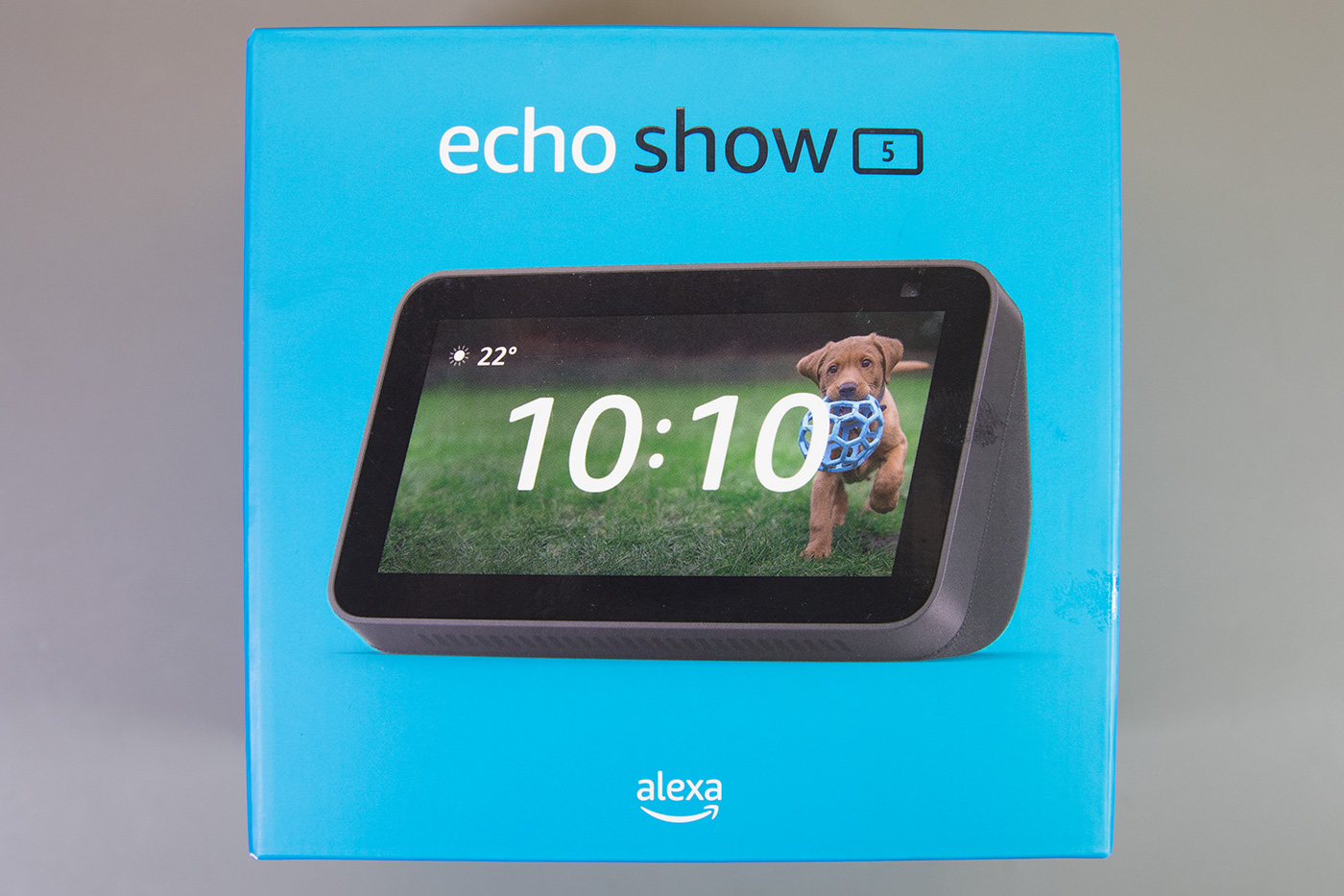
We previously tore down several Amazon Echo devices, including the 3rd gen Dot, 3rd gen Dot with Clock, the Flex, Echo Dot 4th Gen and the Echo Input. In this teardown, we will look at the new Echo Show 5, 2nd 2021 release, a smart display with Amazon Alexa and a 2 MP camera.
The Echo Show differs from the previous Echo devices that we have torn down as this has a large display and camera in addition to the microphones and speaker on the smaller models.
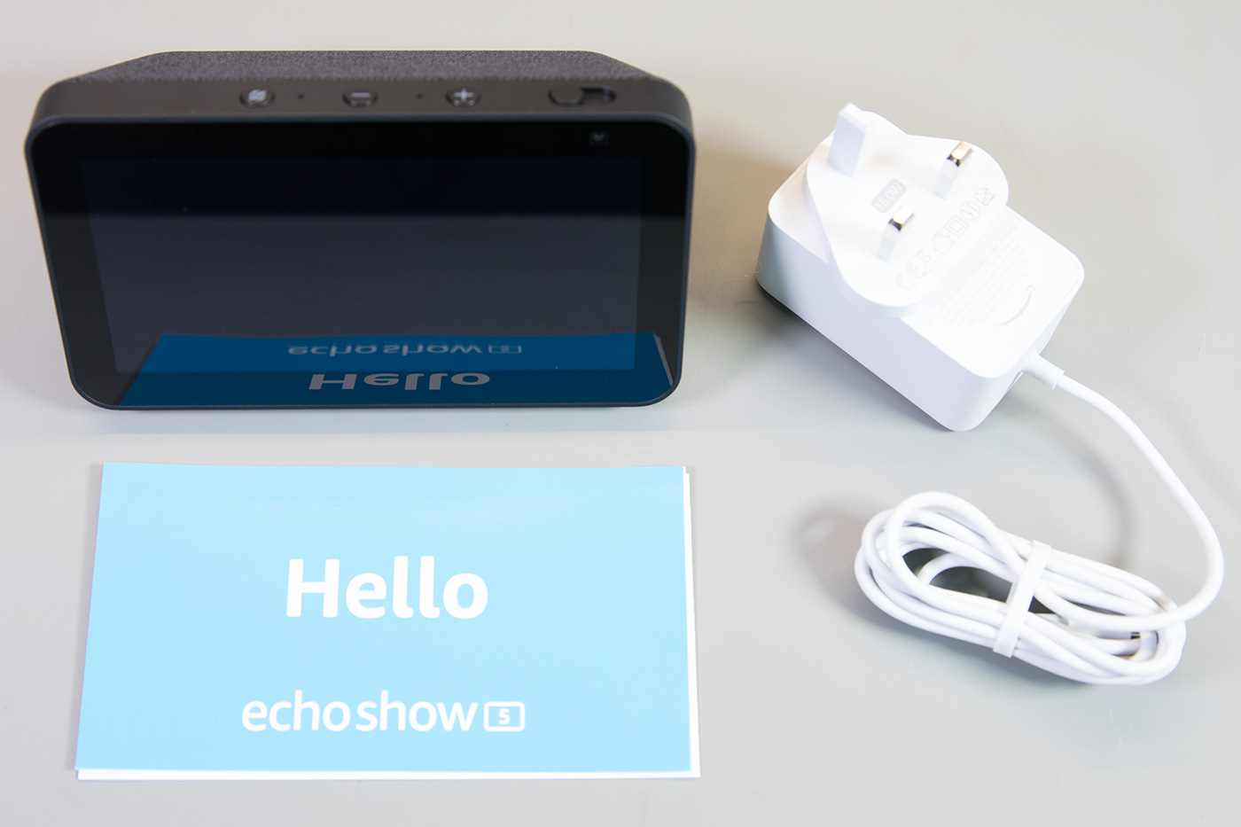
In the Box
- The Echo Show 5
- 240V UK power supply
- Setup instructions
Specifications
The Echo Show 5 (2nd generation) has the following specifications:
- Screen: 5.5 inches with 960 x 480 resolution
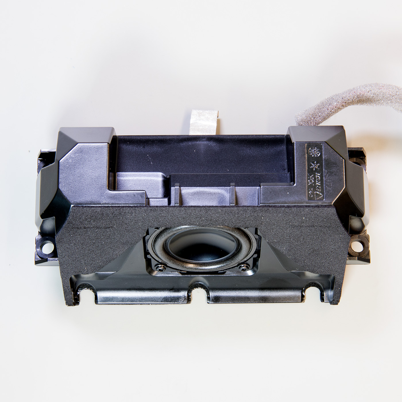
- Speaker 1 x 1.6 inch
- Camera: 2 megapixels
- Camera Controls: Built-in camera cover and Microphone/Camera Off button
- Dimensions: 148 x 86 x 73 mm (W x H x D)
- Weight: 410g
- Wi-Fi: Dual-band Wi-Fi supports 802.11a/b/g/n/ac Wi-Fi networks.
- Processor: MediaTek MT 8163
Top of the Echo Show
The top of the echo has three push buttons, two microphones and a slide switch. The + and – buttons control the volume, and the circle with a line through it enables or disables the microphones. The slide switch moves a white shield cover over the camera.
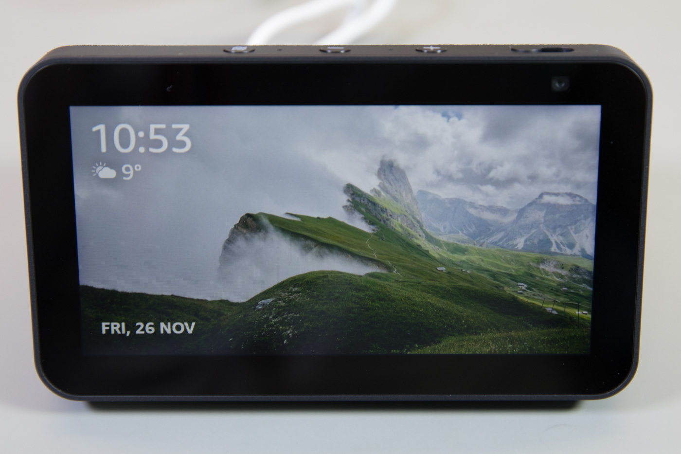
Front of the Echo Show
The front panel contains the LCD touchscreen and a camera in the top right corner.
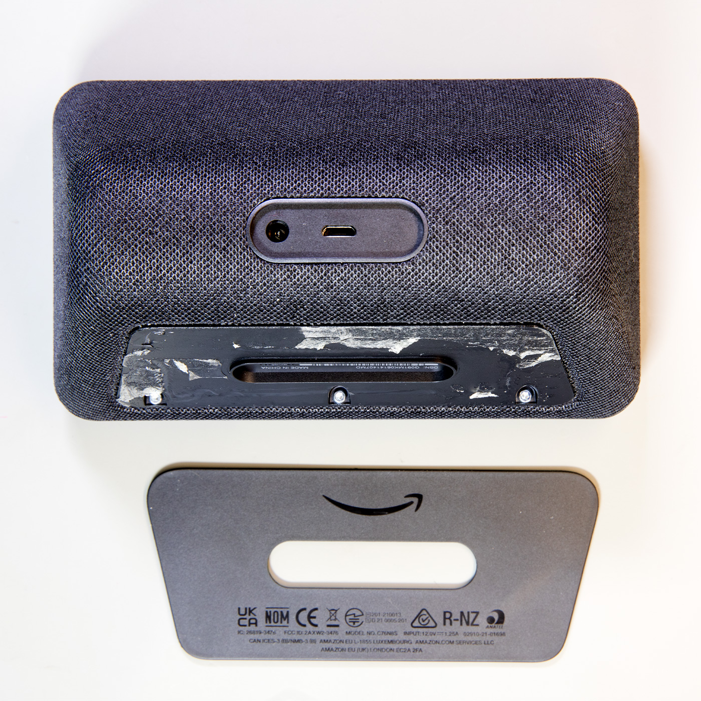
Back of the Echo Show
The back contains a power socket and a USB connector. The USB connector allows connection to a computer where the Echo Show appears as a file device.
Opening the Case
To open the case, first, you need to remove the non-slip aluminium/rubber cover on the base of the echo show using a thin knife or some other flat-bladed tool. Slide the knife around the central piece of plastic to release the adhesive tape. If you try to lift the cover from one end without first releasing the tape, you will crease the aluminium, which may make it difficult to fit back down later.
Under the cover, you will find three T6 Torx bolts which need to be removed.
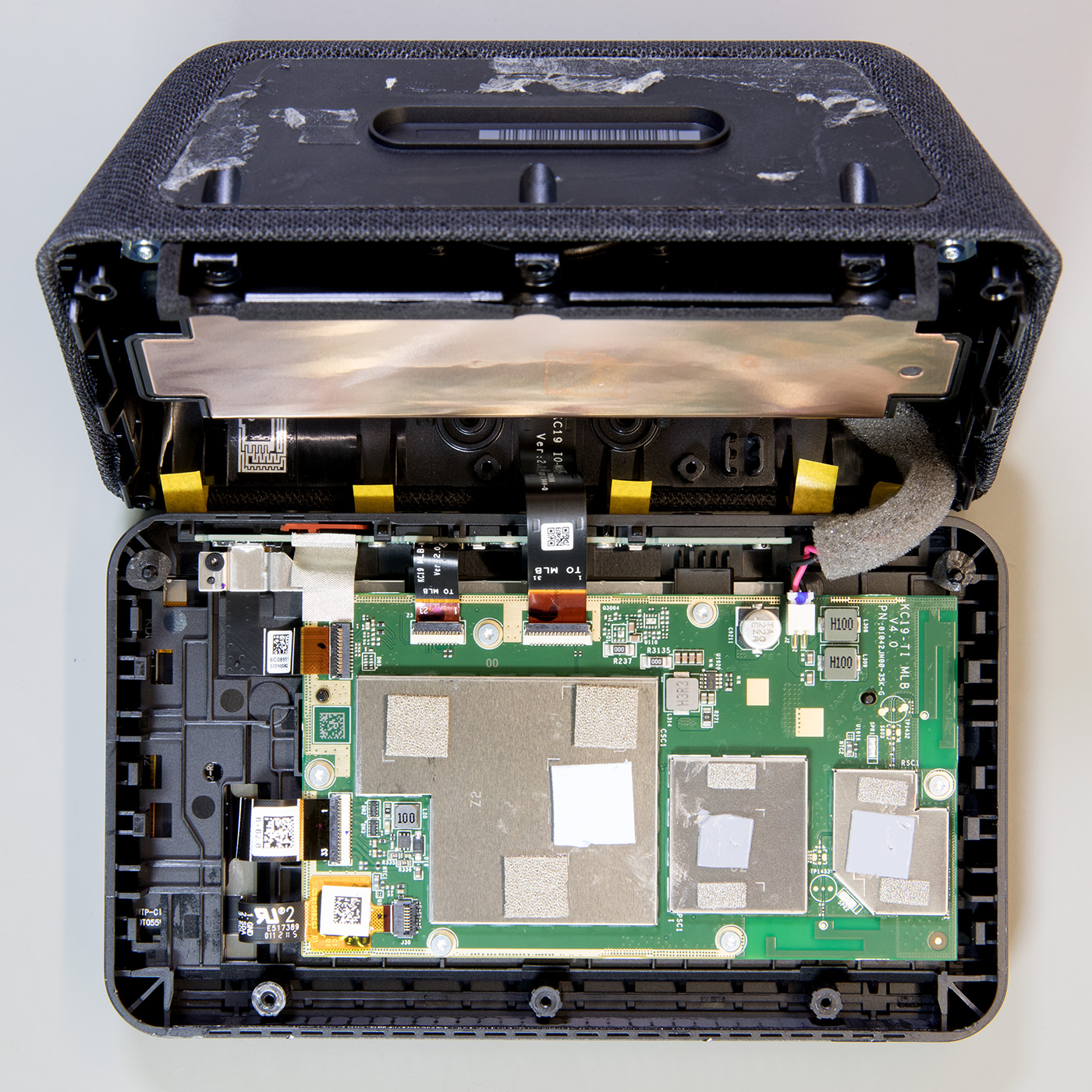
The two halves of the case are separated by prising the front away from the back with a thin blade inserted into the gap around the edge between the material and the plastic front.
Remove the J1 ribbon cable and the J2 speaker cable to separate the screen and front panel from the rear section of the case.
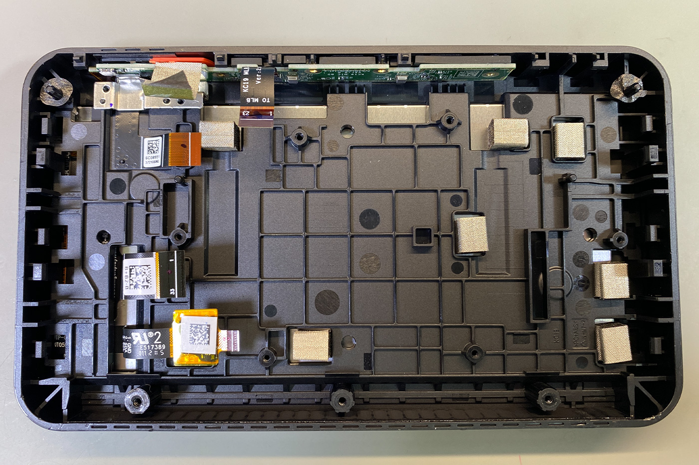
Back section Disassembly
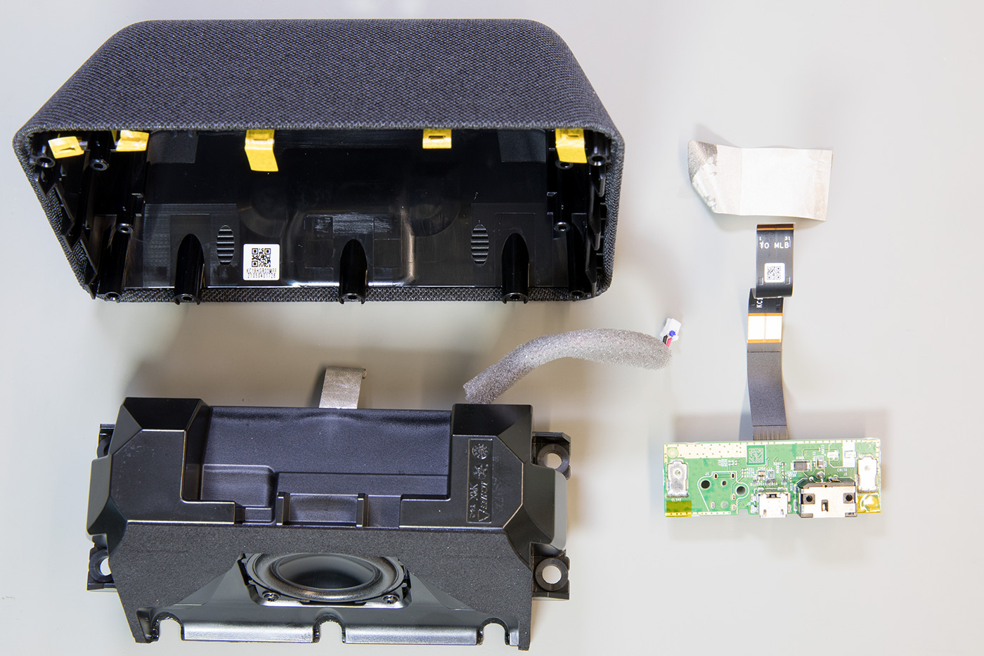
Remove four screws from the speaker assembly and two pieces of conductive tape.
Slide the speaker out of the rear enclosure.
Front section Disassembly
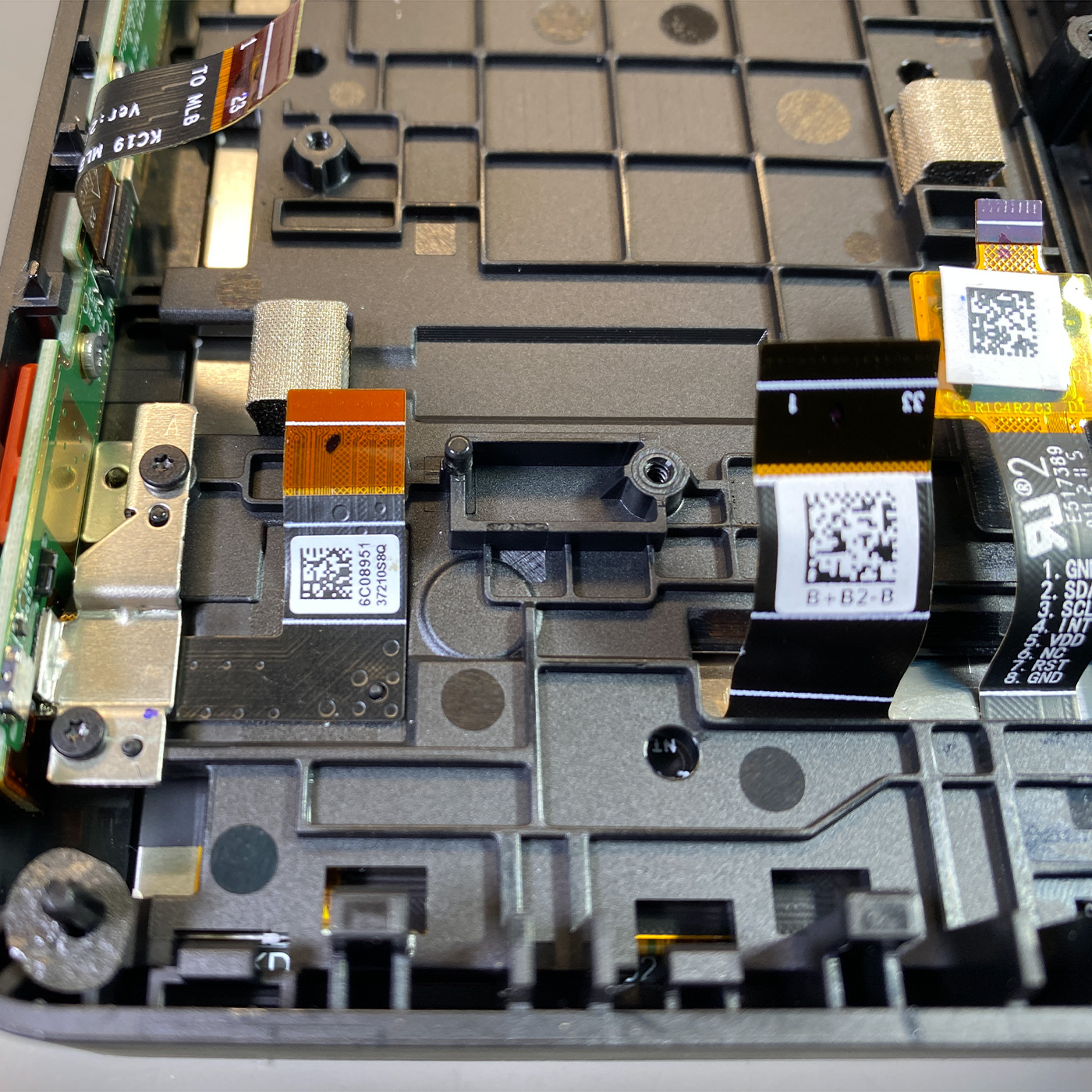
Remove the four ribbon cables, 5 screws and conductive tape to remove the main PCB.
Remove the 4 screws from the button PCB and the two screws from the metal bracket holding the camera down.
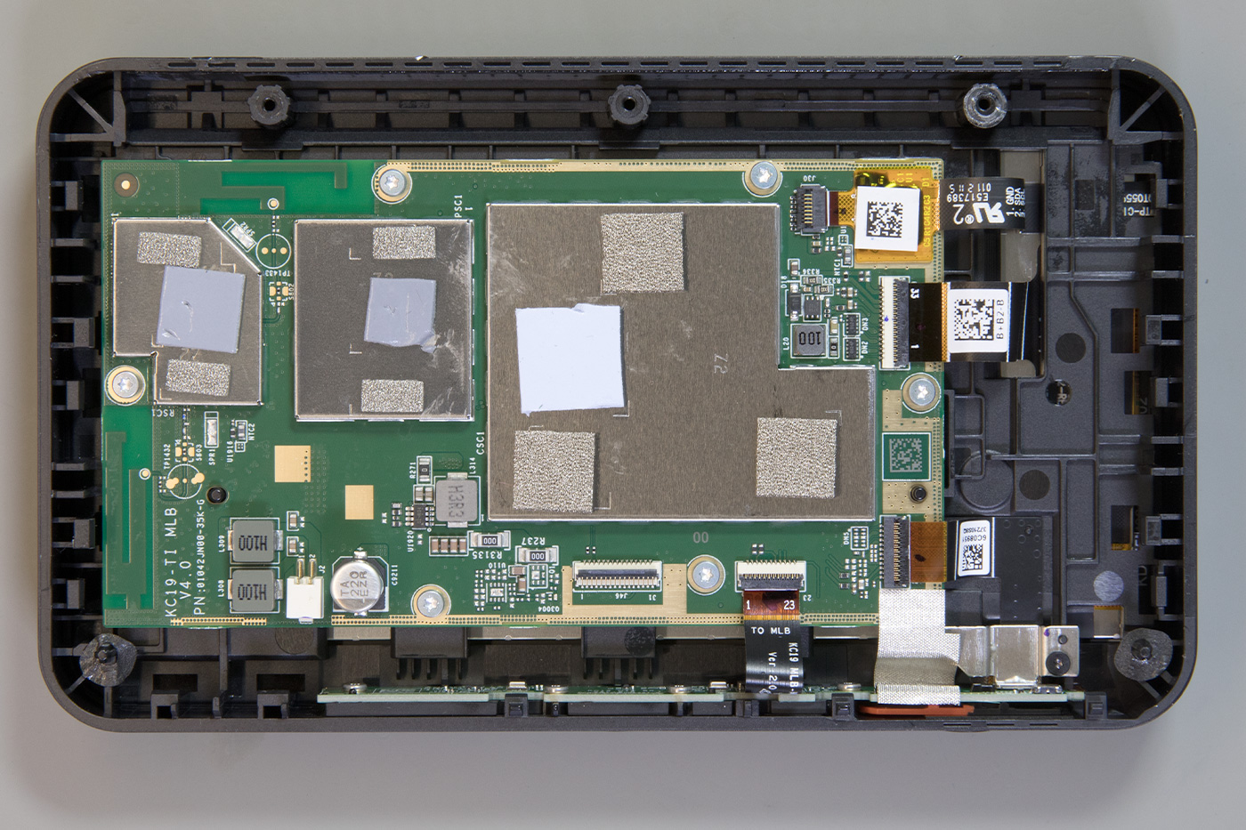
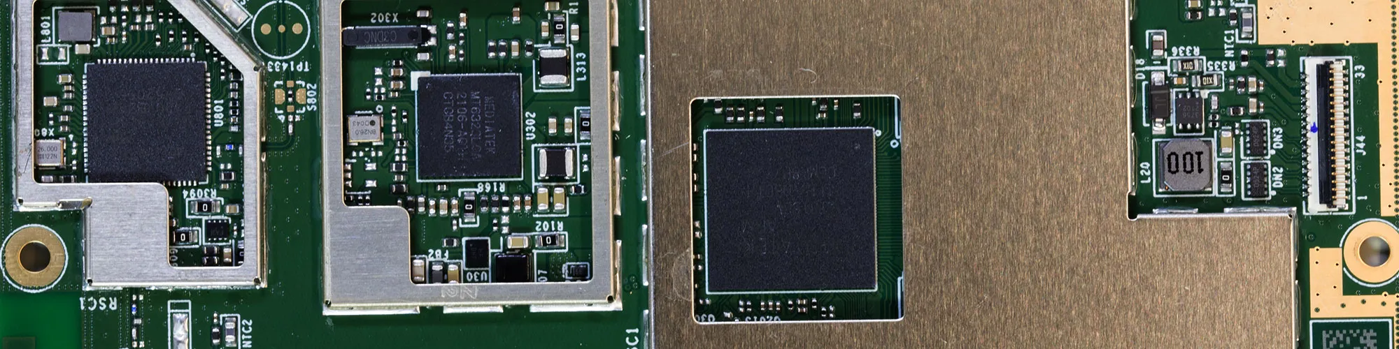
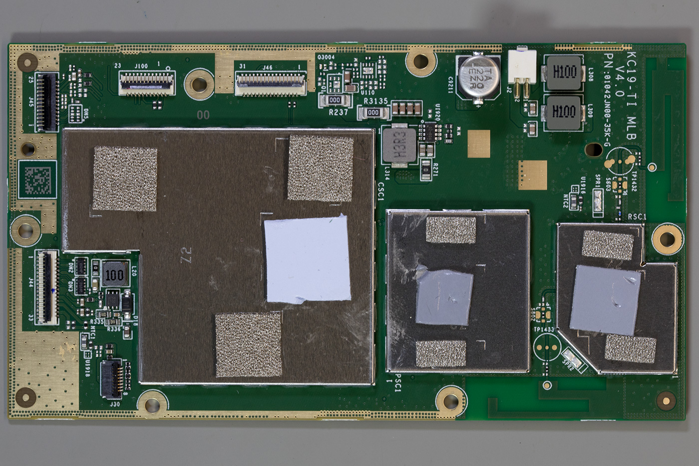
The upper side of the Processor PCB
The upper side of the processor PCB contains the main components for the device.
Around the outside edge are connectors for the touch screen, LCD, camera, power, USB and speaker.
The main processor is a MediaTek MT8163. The MT8163 is a highly integrated SOC with a 64-bit quad-core ARM Cortex-A53 MPCore, 3D graphics (OpenGL ES 3.1), a 13-megapixel camera interface, DDR3/L up to 800MHz and high-definition 1080p video decoder.
A MediaTek MT6323 performs power management on the device.
Communication with the outside world is done using a MediaTek MT7668 dual-band 802.11ac Wi-Fi with MU-MIMO and Bluetooth 5.0 controller.
There is a large metal shield soldered to the PCB. This covers up the DDR3 memory and flash memory chips. We have had mixed success removing these shields in the past, and on one previous Echo model, the flash memory came off with the shield. We don't want to destroy the Echo until we have done some more experiments, so we decided to leave the shield in place.
Alongside the main chips are several smaller power regulators, inductors and capacitors.
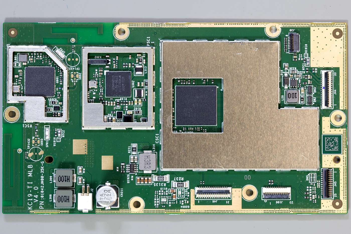
The lower side of the Processor PCB
The lower side contains two ICs and several voltage regulators.
Audio input is controlled with a Texas Instruments TLV320ADC3101 low-power Stereo ADC With Embedded miniDSP.
Audio output is provided using a Texas Instruments TAS5805M 23-W Class-D Audio Amplifier.
There is an unpopulated set of 10 pads in the middle of the PCB, which looks like space for a connector. This is underneath the processor, so it could be a debug or JTAG header and may be worth further investigation.
The lower side is covered in test points. These are not accessible when the device is powered and connected to the LCD, touch screen and camera, so we will have to find a way to access them before we can discover what each test point does.
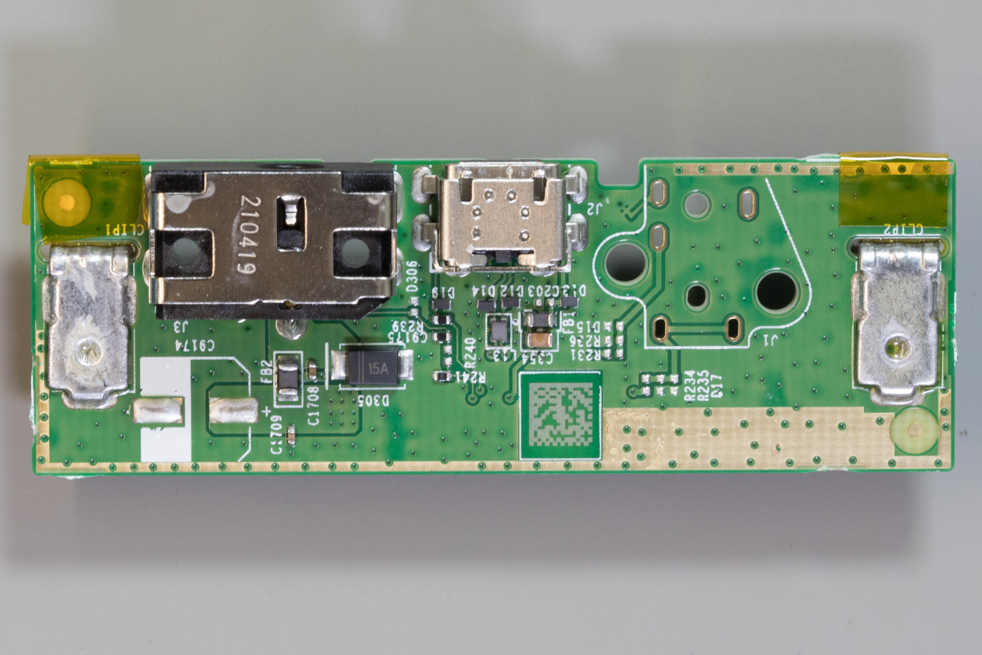
Power and USB PCB
A small PCB is fitted to the rear of the enclosure behind the speaker. This PCB contains a power socket, a USB micro socket and several discreet components.
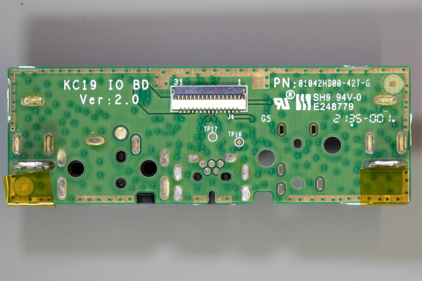
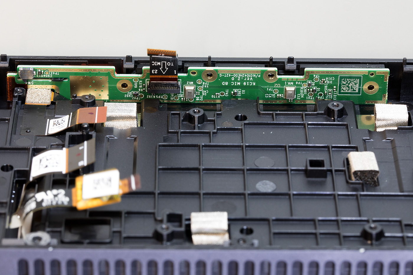
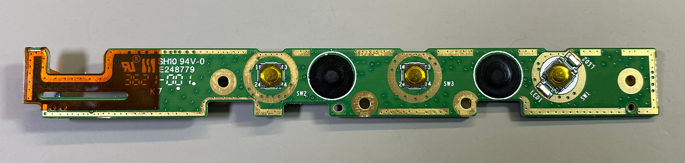
Button PCB
At the top of the device is a narrow PCB containing three push buttons and two MEMS microphones. It was not possible to remove the camera without first removing this PCB.
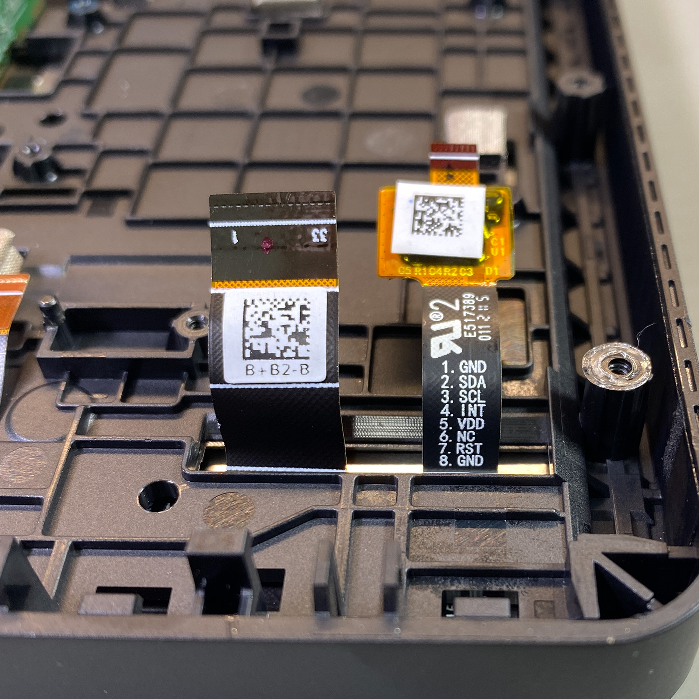
LCD and Touch Screen
We could not find the part numbers for the LCD and touch screen without removing them from the front of the plastic case. As they are glued in, and we don't want to risk damaging the screen, we decided against trying to disassemble that part of the device.
The LCD is a 5.5-inch display with a 33-pin flat flex cable.
After searching the internet, the closest model we could find was a KD055M39-33TH-A001 with a MIPI interface. The display is advertised as a replacement for the Echo Show 5, so it is either the same display or one that is compatible. The specifications for this display are as follows.
- Size (inch): 5.5
- Resolution: 480*960
- Panel type Display mode: IPS
- Interface support Interface: MIPI (33pin)
- Outline (mm): 82.82(H)*144.56(V)*3.24(T)
- Display area size Active area(mm): 61.88(H)*123.75(V)
- Brightness (nits): 350TYP
The touch screen has a part number of E517389, which we could not find on google, but it does have the pinout printed on the cable. It appears to be an I2C-based device with a touch controller built into the flat flex cable. The pinout is as follows.
- Ground
- SDA
- SCL
- Interrupt
- Vdd
- Not Connected
- Reset
- Ground
Power Consumption
We took the following power measurements using our HOPI energy meter.
4.3W with screen wallpaper
4.8W when playing music on Spotify
4.9W when playing a full-screen YouTube video
USB interface and Boot Modes
Connecting the USB socket on the device's rear to a PC allows the Echo to mount on the host computer as a disk drive. The USB socket can also be used for flashing the firmware and other software operations.
The following boot modes are available when powering on the device:
- Holding down - button boots into safe mode.
- Holding down + and - on boot loads fastboot mode.
- Holding down mute and - on boot loads factory reset mode.
Running the Linux command "lsusb -v" gave us a list of USB devices connected to the PC, and in the list was an Amazon Alexa device with the following details.
Bus 005 Device 009: ID 1949:01e1 Lab126, Inc. Alexa
Device Descriptor:
  bLength                18
  bDescriptorType         1
  bcdUSB               2.00
  bDeviceClass            0
  bDeviceSubClass         0
  bDeviceProtocol         0
  bMaxPacketSize0        64
  idVendor           0x1949 Lab126, Inc.
  idProduct          0x01e1
  bcdDevice           ff.ff
  iManufacturer           1 Amazon
  iProduct                2 Alexa
  iSerial                 3 xxxxxxxxxxxxxxxxxxxx
  bNumConfigurations      1
  Configuration Descriptor:
    bLength                 9
    bDescriptorType         2
    wTotalLength       0x0027
    bNumInterfaces          1
    bConfigurationValue     1
    iConfiguration          0
    bmAttributes         0xc0
      Self Powered
    MaxPower              500mA
    Interface Descriptor:
      bLength                 9
      bDescriptorType         4
      bInterfaceNumber        0
      bAlternateSetting       0
      bNumEndpoints           3
      bInterfaceClass       255 Vendor Specific Class
      bInterfaceSubClass    255 Vendor Specific Subclass
      bInterfaceProtocol      0
      iInterface             17 MTP
      Endpoint Descriptor:
        bLength                 7
        bDescriptorType         5
        bEndpointAddress     0x81  EP 1 IN
        bmAttributes            2
          Transfer Type            Bulk
          Synch Type               None
          Usage Type               Data
        wMaxPacketSize     0x0200  1x 512 bytes
        bInterval               0
      Endpoint Descriptor:
        bLength                 7
        bDescriptorType         5
        bEndpointAddress     0x01  EP 1 OUT
        bmAttributes            2
          Transfer Type            Bulk
          Synch Type               None
          Usage Type               Data
        wMaxPacketSize     0x0200  1x 512 bytes
        bInterval               0
      Endpoint Descriptor:
        bLength                 7
        bDescriptorType         5
        bEndpointAddress     0x82  EP 2 IN
        bmAttributes            3
          Transfer Type            Interrupt
          Synch Type               None
          Usage Type               Data
        wMaxPacketSize     0x001c  1x 28 bytes
        bInterval               6
Device Qualifier (for other device speed):
  bLength                10
  bDescriptorType         6
  bcdUSB               2.00
  bDeviceClass            0
  bDeviceSubClass         0
  bDeviceProtocol         0
  bMaxPacketSize0        64
  bNumConfigurations      1
can't get debug descriptor: Resource temporarily unavailable
Device Status:     0x0001
  Self Powered
The Lab126 in the device description relates to Amazon Lab126 (sometimes known as Lab126), an American research and development and computer hardware company owned by Amazon.com.
Holding down + and - while turning on the device boots the Echo Show into fastboot mode.
Running the command "fastboot getvar all" returned the following:
(bootloader) 	antirback_tee_version: 0x0104
(bootloader) 	antirback_lk_version: 0x0103
(bootloader) 	antirback_pl_version: 0x0103
(bootloader) 	rpmb_state: 1
(bootloader) 	lk_build_desc: 7b1780d-20210416_071610
(bootloader) 	pl_build_desc: 29ba1b5-20210311_160043
(bootloader) 	secure: yes
(bootloader) 	prod: 1
(bootloader) 	otu_code: xxxxxxxxxxxxxxxxxxxxxxxxx
(bootloader) 	unlock_status: false
(bootloader) 	unlock_code: xxxxxxxxxxxxxxxxxxxxxxxxx
(bootloader) 	serialno: xxxxxxxxxxxxxxxxxxxxxxxxx
(bootloader) 	max-download-size: 0x6d00000
(bootloader) 	off-mode-charge: 1
(bootloader) 	warranty: no
(bootloader) 	kernel: lk
(bootloader) 	product: CRONOS
(bootloader) 	version-preloader: 0.1.00
(bootloader) 	version: 0.5
all: Done!!
Fastboot can see the device, but we can not extract or update the firmware image as the bootloader is locked.
Future Investigations
So far, we have disassembled the Echo Show 5 and found the main components. We have not decided what the next steps will be, but we have a couple of options.
First, we can reverse engineer the main PCB to find out what the test points and unpopulated connectors are for. If we can find a way of interfacing with the header on the underside of the PCB or removing the shield without damaging the components underneath, we may be able to extract the firmware. We have done this on two Echo devices, one with an emmc flash memory and another with an SPI NAND flash chip.
Once we have the firmware, we can figure out how it works and look for ways to modify it to run our own software.
The second option is to scrap the existing CPU PCB and build a new board with a Raspberry Pi 4 compute module. We will need to find a way of interfacing the LCD and touch screen, add an audio ADC and DAC for the microphone and speaker and write some software to run on it, but this would allow us to use other voice assistants like Mycroft. The biggest difficulty with this option at present is getting hold of a Raspberry Pi 4 compute module, as nobody has them in stock.


Sue
How do you fix an Alexa echo 5 as I have tried holding the mute and minus down for 15 seconds and it still won’t come on thanks
George
Very interesting! Do you think it would be possible to connect the screen (& touch screen) to the motherboard of another android device, so that the other device could use the Echo Show's screen? The reason I ask is that I have found that the echo show 5 fits perfectly into the recess of my 2003 car's old satnav! But the Echo Show doesn't do a great job as a replacement. So ideally I'd have an android tablet or phone there, but the dimensions just don't work.
rlueder
I came across your post while looking for a teardown after unsuccessfully trying to replace Fire OS with a standard Android install. I was hoping someone would have some pointers on connecting speaker, microphone and LCD to a Pi Zero as it's small enough to hide inside the casing. Looking forward to future posts!
Dieter
Nice job! Thanks for sharing.
As a next step, what about soldering an audio cable to the "Power and USB PCB" board in order to make available an line-out-audio that was removed from 1st generation? It looks like the PCB haven't changed from previous version, so I guess the audio signal should be available there? Nearby R231, R234, R235, R236, C15 & C17, perhaps?
Voiceless
I am attempting to do your second option for next steps. Have you attempted it yet yourself? Additionally, I am having difficulty disconnecting the touch screen ribbon cable from the processor PCB; it appears to be adhered. Do you have any recommendations for removal or was yours not glued down?
Doginabag
On the power and USB board there is an unused space which I assume was for the 3.5mm output on the 1st gen. Could a 3.5mm connector be added to the board to obtain an audio output, or is there more to it than that?
Brian
I am not sure if the audio hardware is on the board to be able to output to a 3.5mm socket
Ray Knight
I was able to remove the large shield on the right of the main board without too much damage. It covers 2 Micron MT41K256M16TW-107:P for a total of 1 GB of DDR3 DRAM and 1 Samsung KLM8G1GETF-B041 for 8GB of eMMC 5.1 Flash. I have a different audio amplifier on my board even though it has the same version markings as yours. Mine has a Maxim MAX98396 20V Digital Input Class-DG Amplifier.
Ray Knight
Regarding adding the 3.5mm connector for audio output, other Amazon devices (such as the Echo Dot) that use similar architecture use a PAM8908 Stereo Headphone Amplifier from Diodes Inc.
Austin
I'm trying to use this as an EMF free device for a baby monitor - I'm using the micro-usb port for ethernet but it's still constantly pinging some RF signals. I'm unsure if it's the wifi or bluetooth. Do you know of any way to disable wifi and/or bluetooth while keeping the wired ethernet in play? Thanks!
Brian
I am sorry but I do not know of any way to disable the wifi or bluetooth
Rob
Any further work on this? Wondering if we can rip out the Amazon hardware and use like ESP32 board with DAC. Also Figuring out a way to use the touchscreen.
Brian
Sorry, havent got any further with it at the moment
user0
hi, have you got any progress on reverse engineering the pcb? i'm currently trying to short the data/clk line to get it into the bootrom, to apply amonet, but i've no idea which testpoint is the correct one
- user0
Brian
I am sorry but we havent got any futher with this pcb
Al
After much research you have proven to be the most detailed oriented and knowledgeable about this devise and probably many others.
I just want to disconnect the mic. I use it as monitor for security camera only and have no use for Alexa to have a microphone in my home. Software mute just doesn't reassure me its not still working in background.
Is there some way to just disconnect it, remove it from the Mircophone and button PBC?
Eternally grateful for your expertise.
Brian
You could remove the microphones from the pcb using a soldering iron to stop the device from being able to listen to any sounds
Al
Wow, thank you so very much for your immediate rrsponse.
I have tried to find the specific mics and location on PCB board from the attached photos but I wonder if its possible to have them pointed out by chance. (Arrows on photo or description). This is a above and beyond request as this is an older post. I hope its not too much to ask for. Thank you kindly for your time
Brian
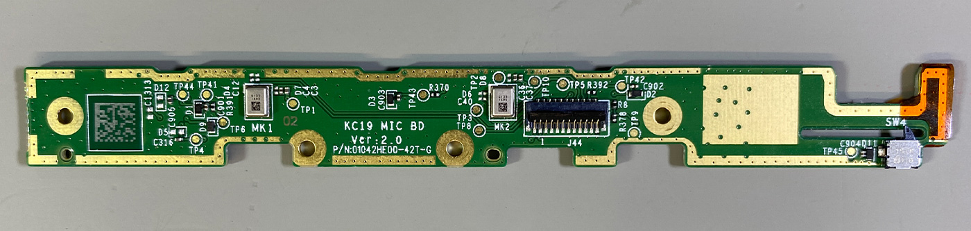
The microphones are marked MK1 and MK2 on the wide microphone pcb.