The DIY soldering robot which we have been building in our spare time over the past few months is now working and we have been able to solder some test Raspberry Pi development board headers with the machine.
Before starting on this robot we looked at the various commercial soldering systems that are available. Wave soldering machines would have been impractical as the connector is on the top side of the board next to the surface mount components. Wave soldering would also coat the full length of the pin in solder which we don’t want to do as it would make it more difficult to stack the boards.
There are several commercial soldering robots available and we got quotes for some of them but we decided that they were either too big, too slow or too expensive, with most costing more than a new car. In the end, we decided that what we wanted was so specialized it would be easier and cheaper to make one ourselves.
We tried to design the machine in a way that would be small and easy to replicate so that if we need to speed up the production of our boards we can quickly make more soldering robots and have a row of them running on a desk. A Bluetooth module was added to the design so when we do build more robots we can use one master robot to wirelessly control several slave machines.
The current speed of the machine is still very slow and the software was set up to allow us to run at a reduced rate so we could easily find any issues with alignment and solder feed. Once we have performed more test runs we will gradually increase the speed of the various stepper drives and feed systems until we can get good consistent soldering.
The previous blog posts detailed the various electronics and hardware stages and this post shows the final parts we had to build, modifications to the solder feeder systems, the software which drives the kflop controller, our custom control boards for the stepper driving and soldering irons elements heating control.
Previous blog posts:
- Antex TCS230 50W Temperature Controller
- Soldering Robot - Head Assembly
- Soldering Robot - Solder Feeder
- Soldering Robot - Temperature Controller
- Soldering Robot - Designing the Motor Driver Board
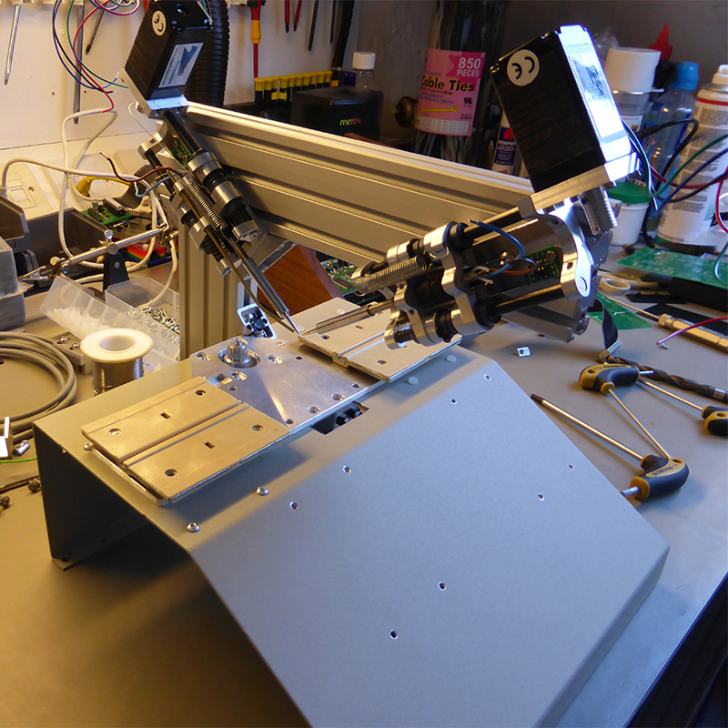
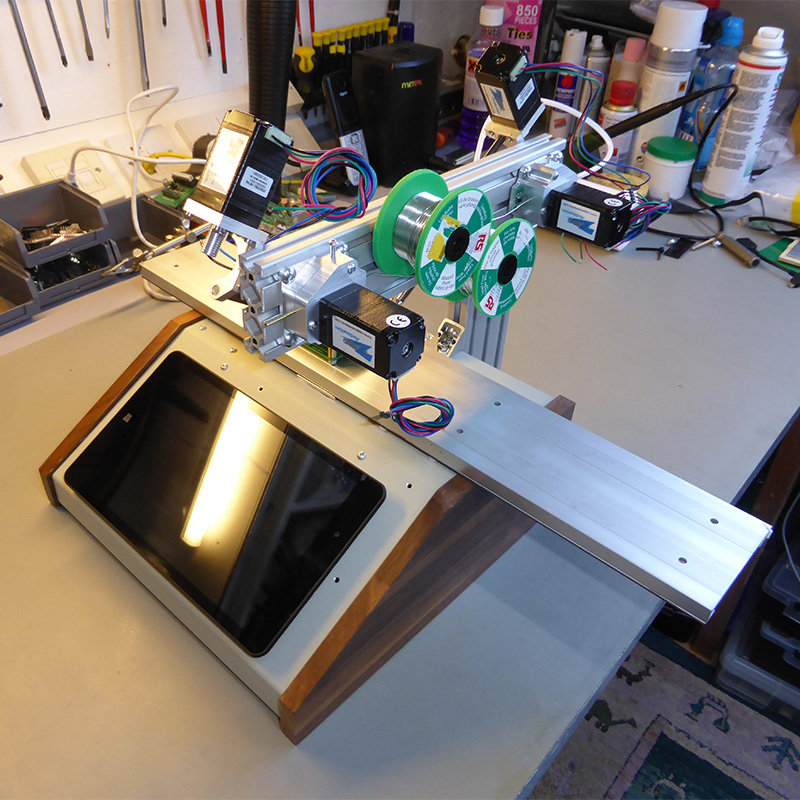
Case Build
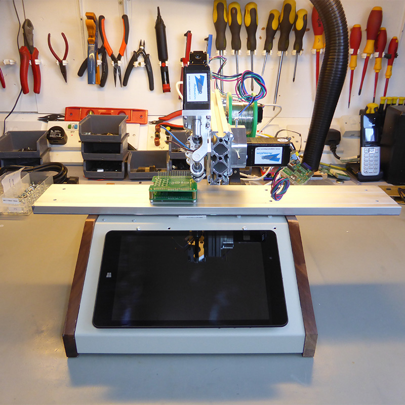
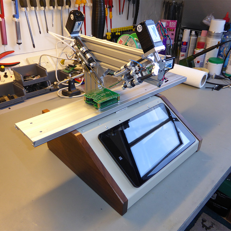
We purchased a sloped instrument case from Farnell for this project as we wanted to be able to fit the Windows tablet computer to the front panel to run the machine. The case has wooden sides which would allow the signal from the Bluetooth module mounted on the control board to escape!
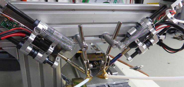
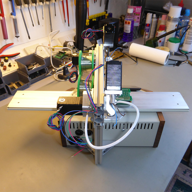
The flat bearings were mounted on 4mm aluminium and this was bolted to the top of the case and the rear vertical arm was fitted to the rear of the case using right-angle brackets to brace the metal against the rear of the case.
Once the bearings were fitted we found a problem with the bearing surfaces being difficult to keep in position due to the bearing material not being fixed to the mounting plates. We decided to replace the bearings with a moulded version which resolved the problems.
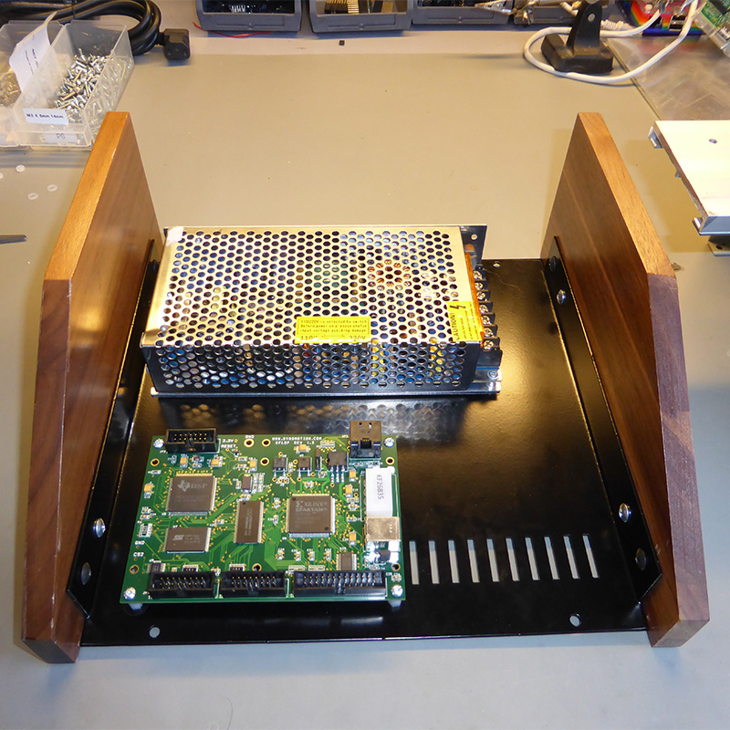
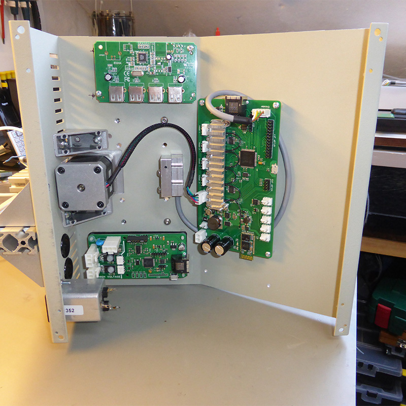
The power supply and the kflop controller board are bolted into the bottom of the case and the interface board, temperature controller and a 4 port usb hub are bolted onto the top of the case. The linear encoder sensor for the magnetic tape was also fitted into the top of the case and this connects to the interface board which is then connected to the kflop controller via a ribbon cable.
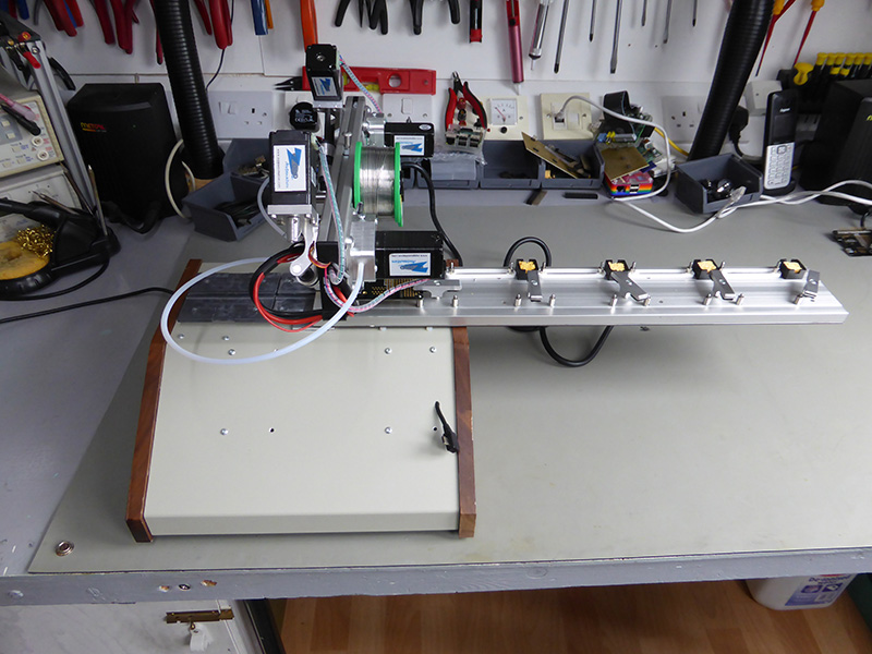
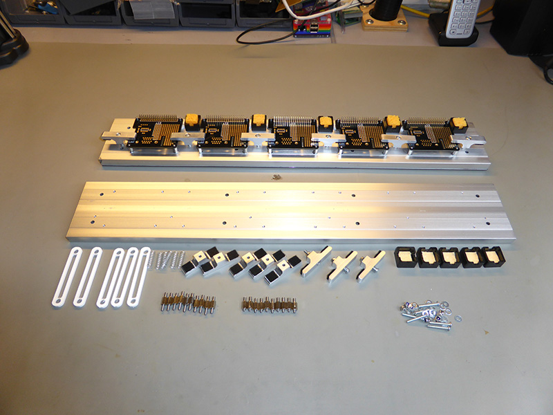
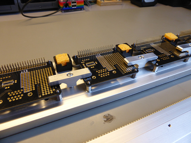
PCB Caddy Rail
The PCBs are held onto the top of the bearing rail using a series of alignment pins and sprung clamps.
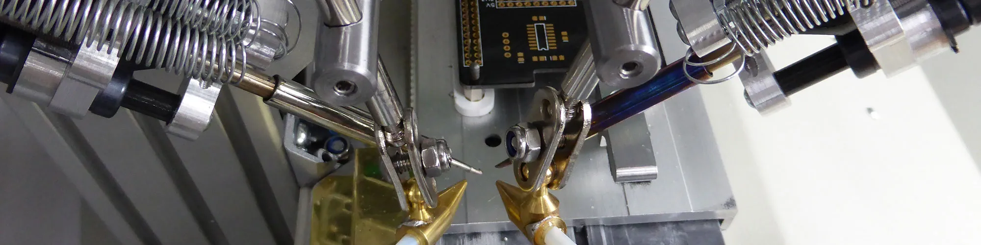
Each PCB has a mounting hole in each corner and this allowed us to easily align the PCB and connector ready to be soldered. The 40-pin header pins are held in small plastic inserts (white in the photos) which hold them in place below the PCB boards.
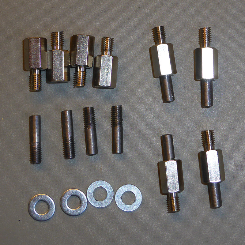
The corner mounting posts were machined from 3mm round steel pins which had an M3 thread added to one end and the other end was turned in the lathe to reduce the diameter to approx. 2.5mm to fit into the holes on the PCBs.
We made small “T” clamps which have a spring in the top to keep constant pressure on the PCB and we used self-adhesive felt pads to stop the clamps from damaging the PCBs being soldered.
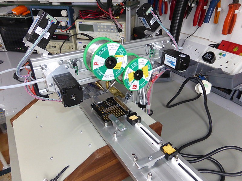
Each of the PCB caddies can hold up to five circuit boards and we have made two of the caddies and so one can be set up as the other is being soldered.
Solder Feeders
We had initially planned to have the solder feed along small brass tubes which were fitted to the soldering iron slide mounts so the solder would be fed and retracted with the iron tips. The first tests of this setup showed several problems with alignment and feed issues due to the brass tube being 2mm in diameter and the solder being only 0.7mm when the solder was leaving the end of the tubes it was not always going in the same direction.
We made a pair of small brass nozzles that had a ball fitting soldered onto the side which allowed us to use parts from a “helping hands” style bench vice to give us to correctly position the nozzles to feed the solder at the proper distance and angles.
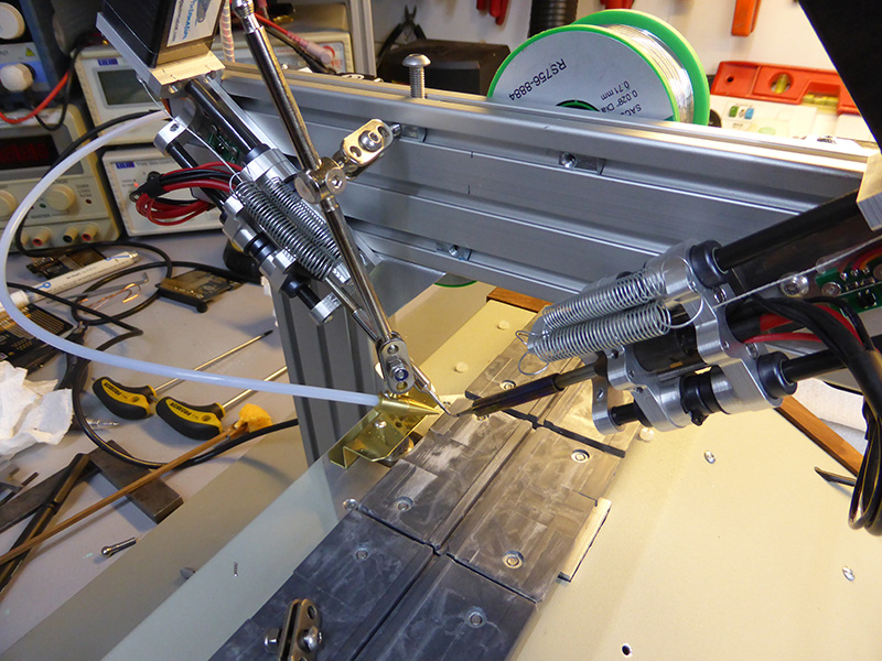
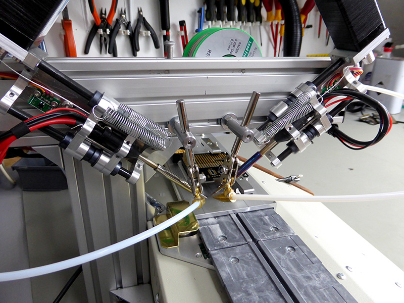
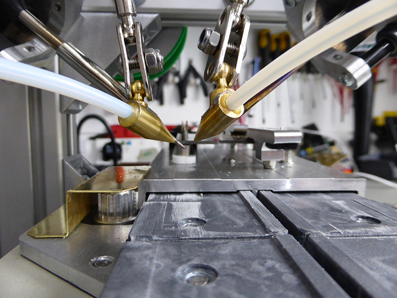
Once we had confirmed the correct position of the nozzles we then machined new steel brackets which used parts from the “helping hands” to connect to the nozzles giving us a limited amount of adjustment of the solder feed. The nozzles are connected to the solder feeder assemblies via a 3D printer filament tube which has a Teflon lining and was sourced from eBay.
Software
The soldering robot is driven via a Windows WPF application which we wrote using Visual Studio 2013.
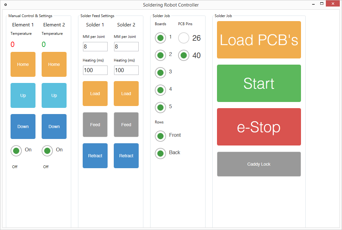
The application screen is split into four zones:
- Manual control of the solder element vertical drives and soldering iron element switching
- Controlling the solder feeds and pre-heating timing.
- PCB and solder job selection.
- Main control buttons for loading the PCB caddy, running a soldering job and emergency stop and caddy release.
Due to the number of settings needed for each of the solder elements and feeders, I decided to create separate C# objects for each which greatly reduced the number of variables being used to keep track of all the current positions and movements.
The software and cad files for the soldering robot project are on my GitHub repository at https://github.com/briandorey/Soldering-Robot-Project
We are currently running the soldering robot via a Windows PC as we found that the Windows 8 tablet we purchased will not charge while acting as a USB host and so the internal tablet's battery was trying to provide power to the USB hub even though it has its own power supply and the tablet was going flat very quickly. We are looking into various ways to resolve this and may have to modify the tablet to replace the battery with an internal switching supply.
The video below shows our first test run of soldering both sides of a Raspberry Pi development board with the 40-pin stacking header pins.
Build Cost and Parts
The BOM (bill of materials) for the electronics are in our GitHub folders at https://github.com/briandorey/Soldering-Robot-Project and the list below shows the parts we ordered and sources for the hardware to build the machine. The cost of the PCB components is approximate as we ordered these from several suppliers and didn't keep track of the individual parts' prices.
| Item | Quantity | Cost | Total | Supplier |
| PTFE Sleeving solder guide tube | 1 | £2.75 | £2.75 | eBay |
| Power Pro Braided rigging line | 1 | £10.00 | £10.00 | |
| NW-02-80 - drylin® N, guide carriage | 3 | £17.56 | £52.68 | Igus |
| NS-01-80 - drylin® N, rails x 500mm | 2 | £32.88 | £65.76 | Igus |
| AWMP-06 - drylin® accessories, precision aluminium shaft 100mm | 4 | £2.42 | £9.68 | Igus |
| RJZM-01-06 - drylin® R - Bearings, closed, standard design (metric) | 10 | £7.10 | £71.00 | Igus |
| NW-12-80 - drylin® N, guide carriage | 3 | £19.99 | £59.97 | Igus |
| 5055396105674 High Accuracy Magnetic Linear Tape 1 m | 1 | £63.20 | £63.20 | Machine DRO |
| Mod 1.0 EN8 Rack 500mm SR10/15/0.5 | 2 | £18.18 | £36.36 | Zapp Automation |
| SY28STH51-0674A High Torque Hybrid Stepper Motors SY28STH51-0674A | 5 | £20.40 | £102.00 | Zapp Automation |
| Spur Gears 1.0MOD - 20° p.a. SS10/14B | 1 | £4.52 | £4.52 | Zapp Automation |
| Zapp Automation Shipping | 1 | £13.50 | £13.50 | Zapp Automation |
| Antex Element To Suit TCS Iron | 2 | £23.78 | £47.56 | Rapid Electronics |
| Antex 1100 2.3mm Bit For CS/TCS Iron | 2 | £3.17 | £6.34 | Rapid Electronics |
| Antex 1101 3mm Bit For CS/TCS Iron | 2 | £3.17 | £6.34 | Rapid Electronics |
| Magnetic Linear Encoder Reading Head - 25 Micron Resolution 5055396105452 | 1 | £70.80 | £70.80 | Machine DRO |
| Aluminium Profile 5 60x20 x 1000mm ART01747 | 2 | £10.93 | £21.86 | Metallin |
| Angle Bracket 5 40x40 Zn ART01790 | 10 | £1.80 | £18.00 | |
| T-Slot Nut 5 St M4 (keyed) ART02830 | 50 | £0.20 | £10.00 | |
| T-Slot Nut 5 St M5 (keyed) - ART02834 | 75 | £0.20 | £15.00 | |
| End Cap 5 60x20 ART01755 | 10 | £0.38 | £3.80 | |
| Angle Bracket Cap 5 40x40 ART01809 | 10 | £0.28 | £2.80 | |
| Miniature Model Bearing MR105ZZ 5X10X4 4255-126 | 20 | £0.47 | £9.40 | Technobots |
| PCB Boards | 1 | £50.00 | £50.00 | JLCPCB |
| PCB Components and Stencils | 1 | £100.00 | £100.00 | Various suppliers |
| Total: | £860.52 |


Dave Gaydos
I enjoy what you guys are usually up too. This sort of clever work and coverage! Keep up the awesome works guys I’ve added you guys to my personal blogroll.
soldering robo
I love this informative content. Thanks.
soldering robo
I love this informative content. Thanks.
soldering robo
Nice Information. Thanks for sharing this content. Visit - https://www.advancetech.co.in/categories/soldering-desoldering/soldering-robo
Premkumar
it's an awesome project, bw how to install the windows software? I would like to give it a try