
For several months now we have been working on a new soldering robot to solder the 40-pin headers onto the raspberry pi development boards we build and sell on our AB Electronics UK website. The mechanical side of the design is almost complete and the temperature controller for the soldering irons is finished so the next stage was to design a driver board for the 5 stepper motors that are used on the robot.
When we designed our pick and place machine we decided to use off-the-shelf stepper drivers and power supply modules as we didn’t have any previous experience designing drivers and switching supplies or soldering small surface mount parts so it was easier to buy ready-made modules instead. This time we decided to build the stepper drivers ourselves. We did this for a couple of reasons, first, it is a lot cheaper to buy the driver ICs and a handful of components than it is to buy ready-made modules and second we wanted to make the soldering robot as small as possible so it would be more space efficient to put 5 drivers onto a single board along with a controller and switch-mode supplies.
After looking around at the different stepper drivers available we settled on the DRV8825 from Texas Instruments. The DRV8825 is a micro-stepping motor driver and can drive up to 2.5A at 8.2V to 45V. It uses a simple step/direction interface and is available in an HTSSOP package so 5 of them could be built into a fairly small area. Most of the stepper motors will be using less than 250mA so 2.5A would be more than enough for this project and the current limit is settable using a resistor and a reference voltage. Micro-stepping ranges from 1 to 32 steps set with three input pins.
Even though the stepper drivers would not be working anywhere near their limits they would still generate heat so we designed and cut out a heatsink on our CNC milling machine. The heatsink is two-sided with a finned block bolted on top of the chips and a block of aluminium bolted between the bottom of the PCB and the enclosure. Hopefully, this will be enough to keep the drivers cool without the need for any fans.
We decided to buy a switch mode supply to drop the voltage down from 240V to 24V which would be used to drive the motors but we decided to design the switching supplies that would drop the 24V down to 5V and 3.3V for the low voltage parts of the robot. Texas Instruments WEBENCH Designer was used to design the power supplies with a TPS54540 used for the 5V supply and an LMR16006XDDC used for the 3.3V.
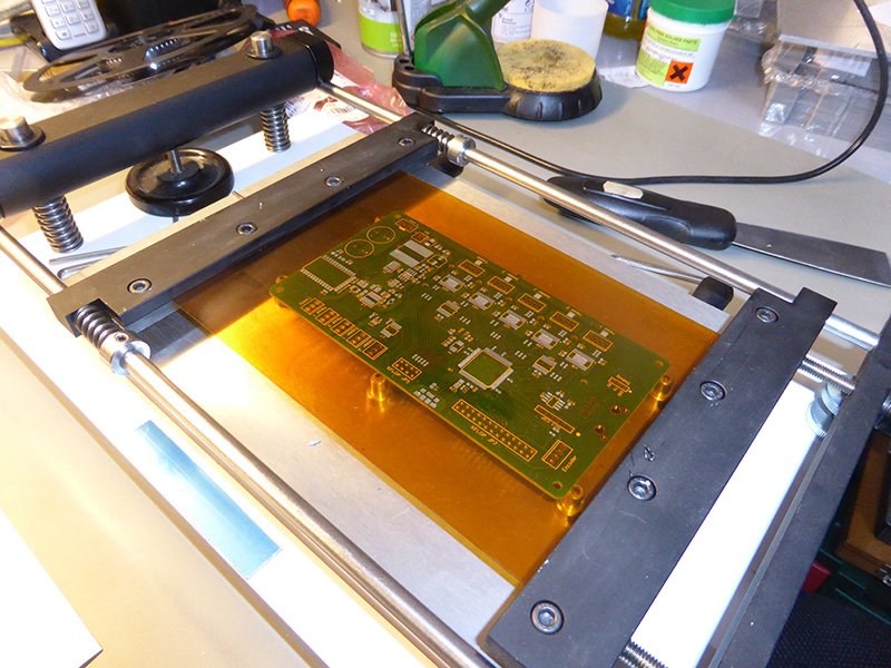
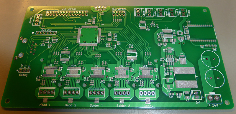
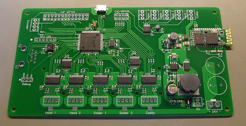
When we came up with the idea of designing a soldering robot one of the requirements was to make it modular and easy to replicate so we could build several robots if necessary. For this robot to save time we are using a kFlop motion controller connected to a Windows tablet to generate the step pulses needed to move the robot, the same system that we use on the pick and place machine. While this machine will use a kFlop controller we wanted the robot to be used without an external motion controller so we decided to use a PIC32 32-bit microcontroller for managing the driver board. This is severely overpowered for how it is being used at the moment, basically relaying temperatures from the temperature controller to the PC and setting the current limits on the motors but it does give us the flexibility to write a motion control engine in the future that can run the robot directly from the PIC microcontroller.
We used the same PIC32 microcontroller on our pick-and-place machine so we could recycle a lot of the code for the firmware speeding up the development of the more complicated parts like the USB stack.
An HC05 Bluetooth module was added onto the driver board so when we do decide to build a second robot we can use the first robot to control the second one wirelessly. In theory, we could have one master robot and a row of slave machines all running together and all controlled from a single tablet PC.
To control the current limits on the stepper drivers we needed to supply each driver with a reference voltage between 0 and 3.3V. To do this we used a pair of MCP4461 digital potentiometers configured as voltage dividers. The MCP4461 contains four non-volatile potentiometers so the values can be set once and will be restored at power up without any user intervention, useful for making sure the correct current limit is set on each driver when we turn the robot on. The MCP4461 also contains 5 bytes of EEPROM which was used to store the micro-stepping settings for each driver. A Windows application was written in .net to configure the driver currents and micro-stepping settings, this will make it easier to fine-tune the motors once the robot is built.
For communication with the PC, we added a USB port and configured the PIC to appear as an HID device in windows. An SN65HVD1474 RS485 controller was used so the driver board can talk to the temperature controller.
Headers were added to the circuit for five optical switches that will be needed to sense the home position of the motors. A magnetic encoder will be used to measure the movement of the caddy that will hold the PCBs for soldering.
Apart from two capacitors and some headers, all of the components on the board are surface mounted with 0603-size parts used for most of the discreet components. We had to use 0402 capacitors around the microcontroller as there wasn’t space to use larger sizes. All of the parts were placed by hand with tweezers so a steady hand was needed, especially on the 0402 parts.
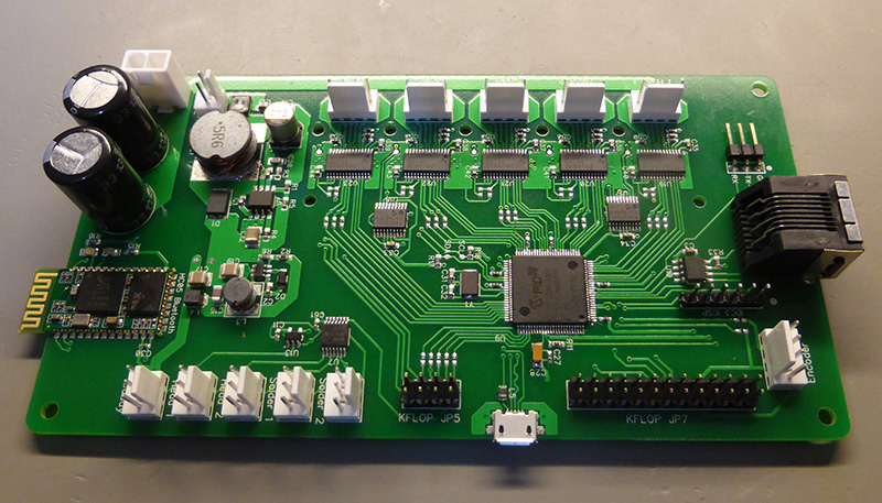
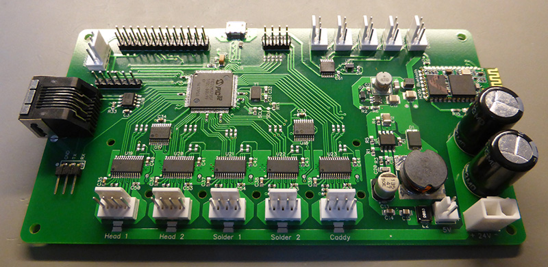
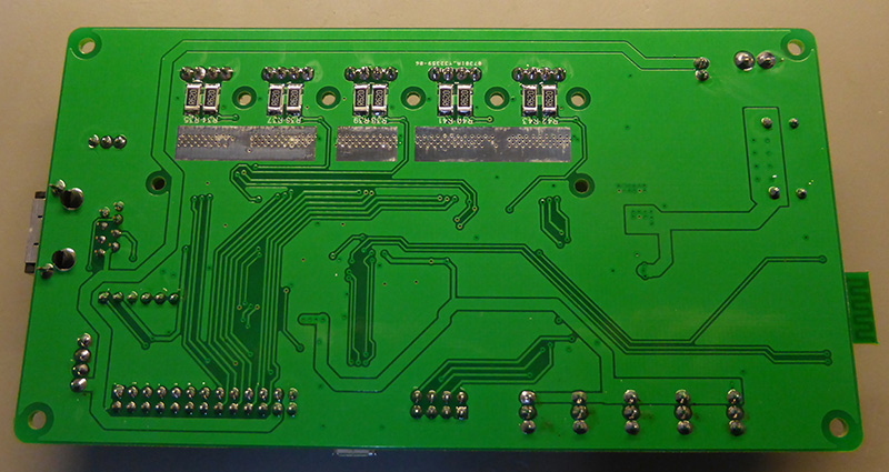
When we designed the driver board we added jumpers between the drivers, inputs and encoder and the PIC microcontroller. The jumpers will be disconnected on the first robot so the PIC doesn’t interfere with the kFlop but it does give us the ability to connect the motors and inputs directly to the microcontroller in future versions.
After the first driver board was built we discovered one problem with our design. The DRV8825 stepper driver IC contains an internal 3.3V regulator that can be used to supply the reference voltage for the current limits. It also has sleep and reset pins that need to be tied high for the driver to operate. When we designed the circuit we made the mistake of using the internal regulator to supply the voltage to the sleep and reset pins. After building the board we found that the drivers start in a sleep state when they are first powered on and in the sleep state the 3.3V regulator is disabled. No 3.3V regulator means no power to the home or resets pins and the driver doesn’t come on. Once we worked out the mistake we carefully cut the PCB tracks between the internal regulator and the sleep and reset pins and tied them instead to the main 3.3V power supply. A lesson for the future, always read every part of the datasheet when using a new device.
With the driver board complete the next stage is to put everything together and begin work on the software to control it.
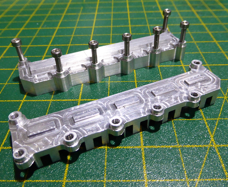
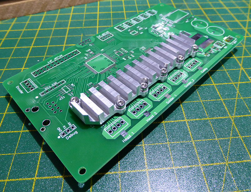
The schematic, PCB layout and firmware for the driver control board can be downloaded from our Git Hub page at github.com/briandorey/Soldering-Robot-Project/
Comments