
We are working on a new project to make a dual-headed soldering robot to automate the soldering of the dual in-line header pins on the Raspberry Pi development boards we design, manufacture and sell on our shop at www.abelectronics.co.uk
We have looked at a lot of commercial soldering robot systems and had quotes for a ready-made unit which start at £30,000 for a basic single soldering head model and they are very slow compared to the speed at which we can solder the header pins by hand and would take up a lot of space in our small workshop.
The plan with the new machine is to have two soldering iron elements which are temperature controlled with a Windows 8.1 tablet via USB to a Microchip PIC processor controller which will send the temperature commands and requests to a separate daughter board which will monitor the temperature of the two soldering iron elements and control the mains electricity via a pair of triacs.
Stepper motor control will use the same kflop controller board as we used on our DIY Pick and Place project with a temperature controller circuit located at the top of the machine and a main interface/controller board to interface with the kflop and have the stepper motor drivers and power supply circuits on the same board. The boards being soldered will go through the machine on a removable caddy so we will be able to have several caddies set up for different soldering jobs and load multiple boards on each caddy.
We decided to use the temperature-controlled elements from Antex TCS230 soldering irons due to the low cost and wide range of the soldering bits. After purchasing an Antex TCS230 soldering iron which the Antex website stated that it had a K-type thermocouple, we made a test circuit with a K Type thermocouple to SPI chip to measure the temperature but we found that the information on the Antex website was not correct and the temperature was actually being monitored by a thermistor with a positive temperature coefficient.
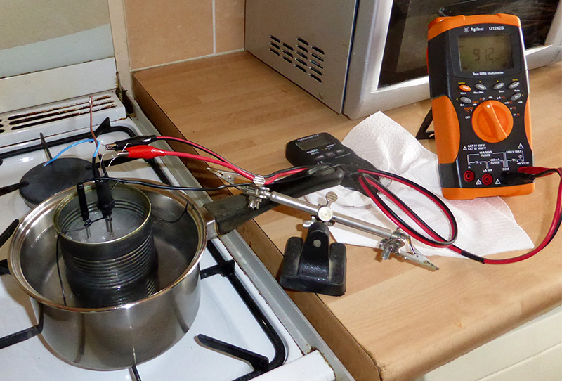
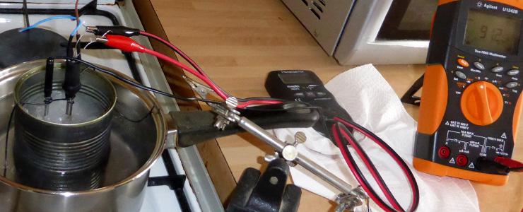
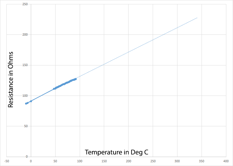
In order to obtain the resistance values of the thermistor with regard to the temperature we used a standalone digital thermometer and using a block of ice in a tin can with holes drilled for the thermometers probe and the soldering iron element we obtained a low measurement of 87 ohms at minus 10 degrees Celsius. We then proceeded to gradually heat the container and recorded the resistance at various temperature points. This was then put into Microsoft Excel to produce a graph and list of the temperature vs resistance measurements and using a trend line on the graph we were able to calculate the resistance at much higher temperatures which we later verified using a second soldering iron to heat the Antex element up to 300 degrees Celsius as shown on the graph image below.
The temperature vs resistance measurements showed a resistance range of between 80 and 325 ohms for a temperature range of -20 to 600 deg C. To measure this we plan to use a Microchip PIC with 16-bit ADCs and a fixed voltage source to enable us to measure the resistance/voltage drop across the thermistor and then calculate the temperature which will then be used by the PIC to control the soldering iron tips.
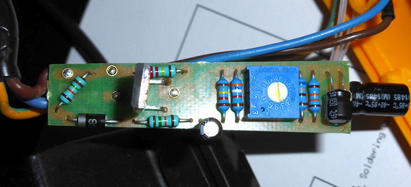
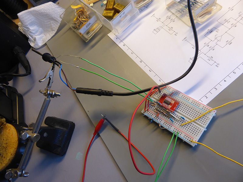
The voltage across the thermistor is very low and so to maximise the sensitivity of the ADC we decided to use an Op-Amp to amplify the signal and also add a low pass filter to remove any 50 Hz mains noise. We are using an OPA4330 1.8V, 35µA, microPower, Precision, Zero Drift CMOS Op-Amp from Texas Instruments (http://www.ti.com/product/opa4330) which is a 4-channel Op Amp model. We made a test circuit on a breadboard (photo below) to test the circuit and after experimenting with various gain resistors we found a combination which gave us the gain we needed to work with the temperature range we require.
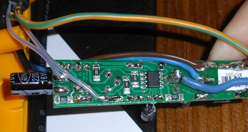
The next stage was to design a temperature controller board using the Microchip PIC and dual inputs for the sensors and mains-controlled outputs to power the soldering iron elements. The board has inputs for USB control and RS458 which will link to the main control board in the soldering robot system. The temperature controller board also has the option to add an LCD display and control buttons so it could be used as a standalone unit if needed.
We are currently waiting for the PCBs to be produced and the next step will be to start designing and machining the hardware for the robot frame and moving parts.


Marian Hancko
what is the size or parameters of the TRIAC please?
I need to replace it but I can't see the numbers on it.
If you could help me.
Thank you
Brian
Marian, i am sorry but I don't have the iron now or know what the part number is for the triac.
Marian Hancko
Brian thank you for info anyway.