After the removal of our Raspberry Pi based home data logger and the installation of the Mosquitto MQTT and Home Assistant Data Logging system in March this year we have not been able to monitor the solar hot water pump status as we did before.
The previous data logger used an analogue input on the Raspberry Pi interface board which was powered by a small 5V power supply connected across the water pump.
As the new computer didn’t have any analogue inputs we had to find a different way to monitor the pump running status. We had considered using a Wi-Fi module as we used in the mains meter and gas meter logger project but that would still need a separate power supply.
Running alongside the hot water pump and controller are the cables for the 1-wire temperature sensors which monitor the solar hot water panel and hot water cylinder after looking at various options for a digital IO chip which would interface with the 1-wire bus we found the DS2413 from Maxim which is a 1-Wire, Dual-Channel, Addressable Switch with Open-Drain and Programmable I/O Pins.
This allowed us to monitor a digital input for the pump running status and this would be read by the software on the server PC and the status saved via MQTT to be accessible by the other software for local reading and also uploading to the home data logger website.
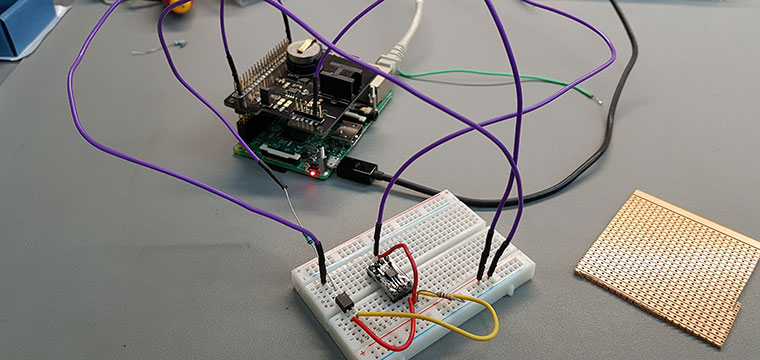
The new circuit was first tested on a breadboard before being built on an offcut of stripboard PCB.
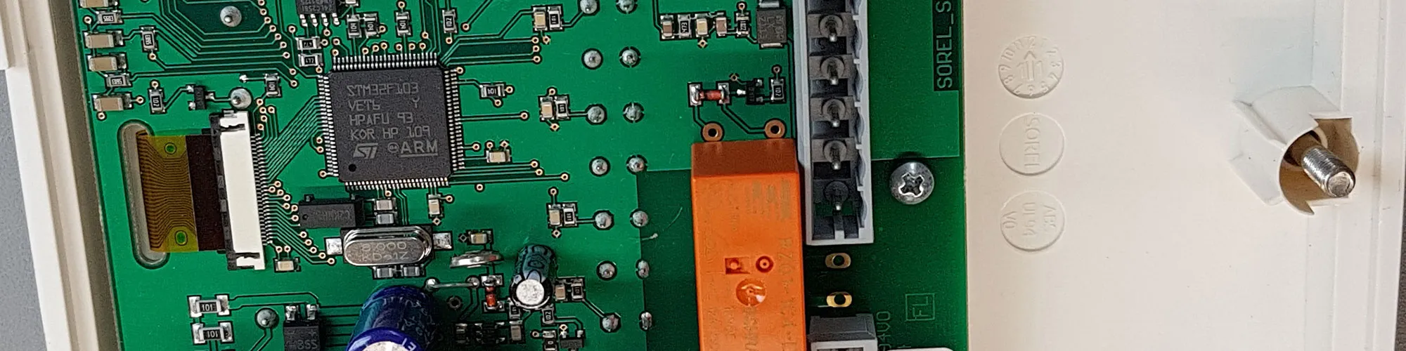
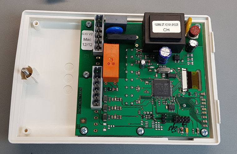
Our home 1-wire setup has 5V, GND and OW cables and we planned to use the 5V power to run the new circuit but after testing the solar hot water controller we found that it had a 3.3V internal supply which allowed us to build and install the circuit inside the existing case and only have an OW and GND connection to the existing 1-wire system.
To monitor the pump running relay we used an optoisolator which then uses a pullup resistor on the DS2413 IO input pin and the optoisolator would pull this to ground when the pump is running.
The 1-wire data from the DS2413 was inverted with 1 being returned when the pump was off and 0 returned when it was running but we inverted this in the software.
As the new circuit only has four components we didn’t feel it was worth the expense of getting a custom PCB made and so we used one of our SOT23-6 breakout boards to mount the DS2413 package and the other components were fitted to a small piece of stripboard.
Inside the solar hot water controller was a 10-pin programming header and this had 3.3V and GND connections and so we used this to power the new circuit.
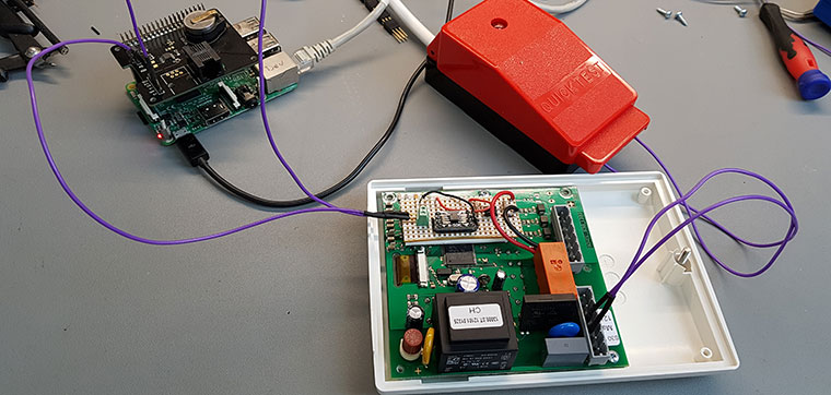
The new circuit fitted into the controller and was tested on the bench and Raspberry Pi with a 1-Wire interface board.
Circuit schematic.


Comments