We needed some reverse polarity SMA Plug terminators to blank off the unused Wi-Fi connectors on our broadband router and also on our desktop computers as we previously had the antennas installed and these sometimes got in the way when changing cables on the back of the computers.
All the commercial ready-made 50-ohm terminators we found online had the wrong type of SMA connector and so we decided to make our own. We needed straight reverse polarity SMA plugs for the terminators and we found a suitable connector and some 1W 50-ohm ceramic resistors from Farnell.
The parts used are:
RSMA1111A1-3GT50G-1-50 - RF / Coaxial Connector, SMA RP Coaxial, Straight Plug from https://uk.farnell.com/amphenol/rsma1111a1-3gt50g-1-50/rf-coaxial-sma-rp-straight-plug/dp/1327442
41F50RE - Through Hole Resistor, 50 ohms, 40 Series, 1 W from https://uk.farnell.com/ohmite/41f50re/res-50r-1-1w-axial-ceramic/dp/2448925
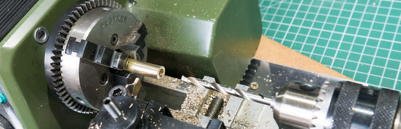
Length of 8mm brass bar for the rear cover shield.
Assembly
The 8mm brass bar was drilled with a 4.6mm drill to a depth of 8mm to and then cut to a length of 11 mm. The end was then drilled with a 1mm drill for the resistor lead.
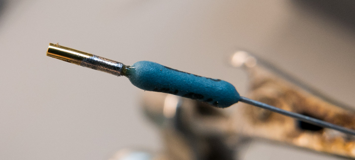
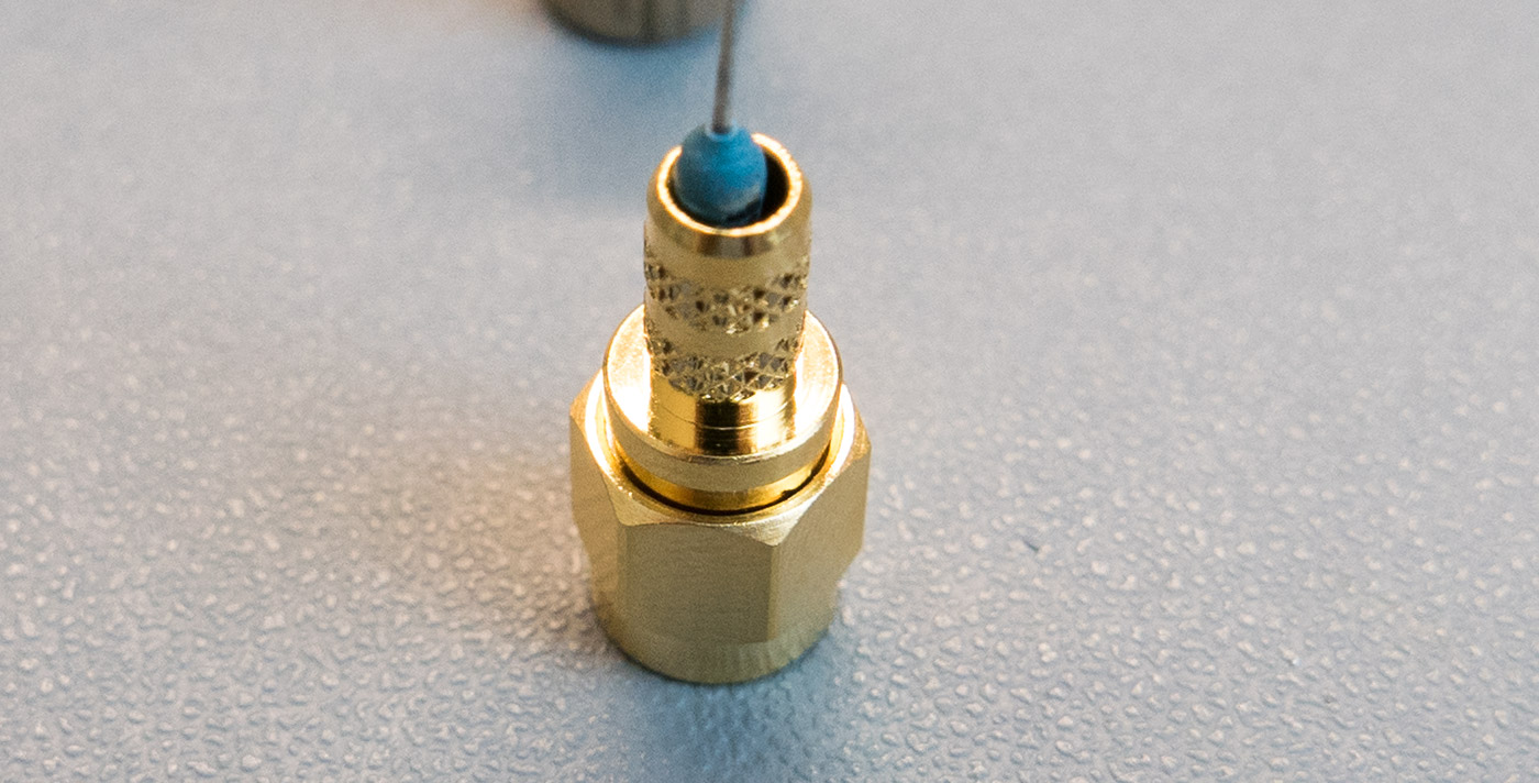
One of the resistor leads was trimmed to approx. 2mm and the centre connector for the SMA plug was soldered to the resistor lead.
This was then inserted into the SMA plug and the new brass cover was slid over and soldered around the SMA plug end and to the end of the resistor.
Once the connector had cooled, the excess resistor lead was trimmed and the end smoothed level using a small file.
We had some old round heatsinks which fitted onto the 8mm brass bar so we installed these onto 3 of the dummy loads to help with the cooling.
As our computers and the broadband router normally have the Wi-Fi turned off these shouldn’t have any current flowing into them but sometimes software updates turn them back on and this will stop any unwanted signals from getting in or out of the devices.
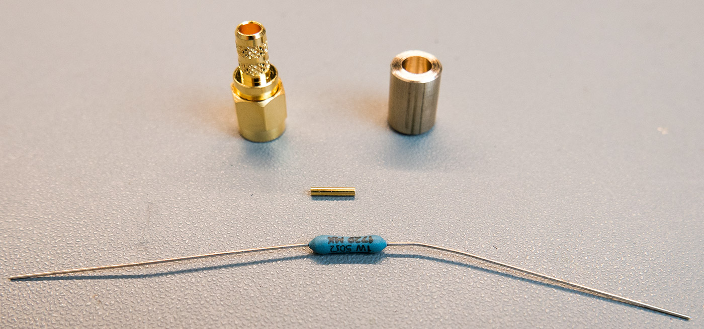
The parts to make the dummy loads
The connector pin was soldered to the resistor lead.
The pin and resistor installed
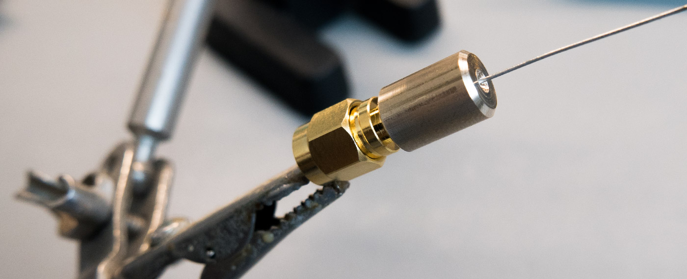
Ready to solder together
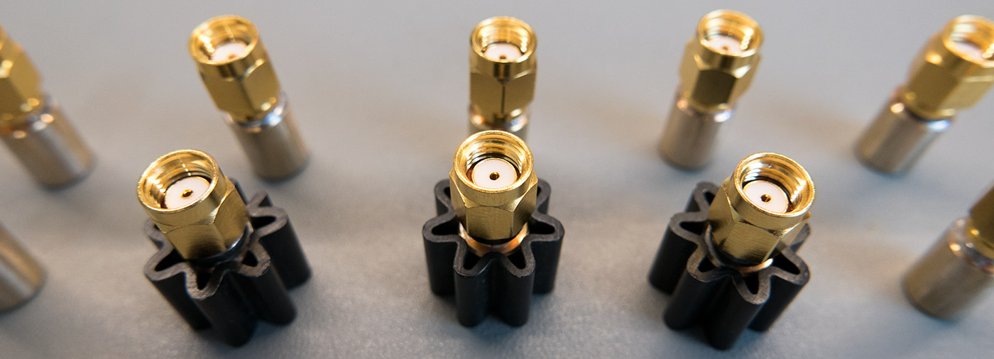
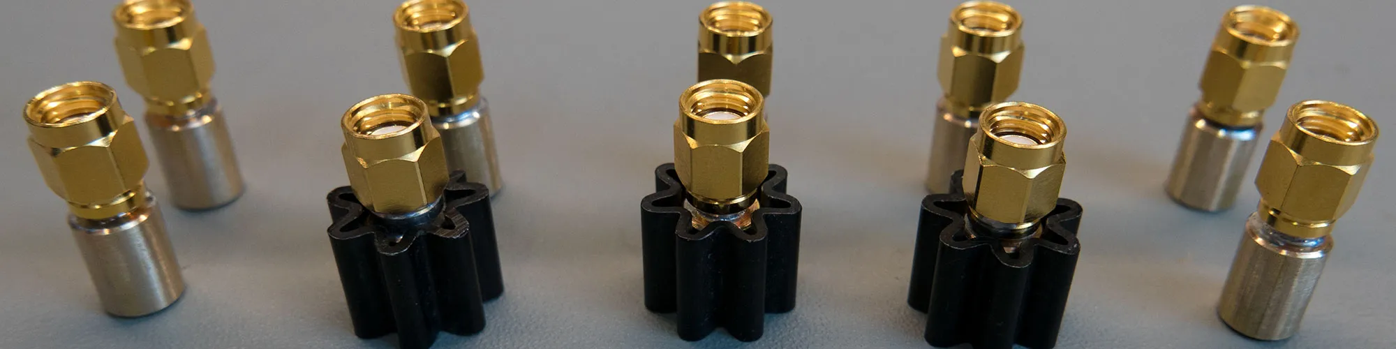
The completed dummy load/terminators with Heatsinks on some for additional heat dissipation.


Comments