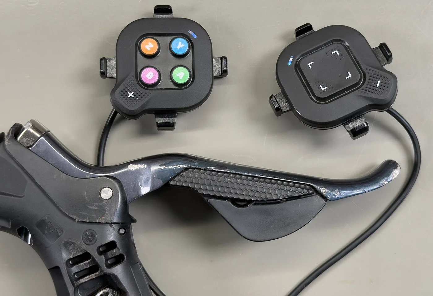
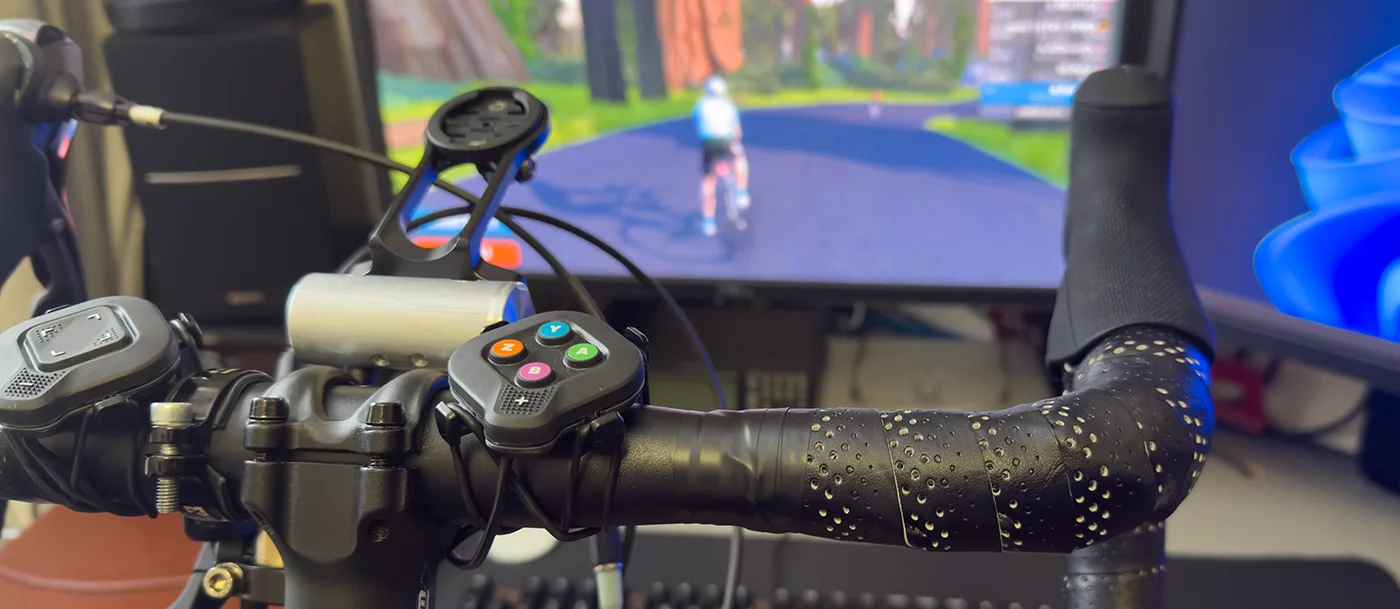
In the previous post, I introduced the Zwift Cog and Zwift Click v2 Controllers kit, which I use with Zwift on my Tacx Neo 2T smart bike trainer.
The controllers are mounted next to the stem on the handlebars, which are easily accessible when riding with your hands on the tops of the bars, but when holding the hoods or drops, it is not possible to change gear without changing hand location, which is difficult when sprinting.
The trainer bike is set up with some basic 9-speed road shifters from an old bike, and they are not connected to the rear derailleur as the cassette is an 11-speed model, I have a separate mountain bike 11 speed shifter mounted to change gears if needed.
Shimano Di2 Shifters
I considered trying to modify the road shifters to add remote switches, but they are not easy to take apart and modify, so I looked for used Shimano Di2 electronic shifters on eBay, which I hoped could be used to control the Zwift click controllers.
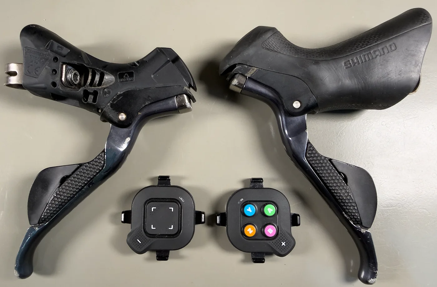
I found a pair of Shimano Ultegra ST-6870 Di2 11-Speed Road Bike Shifters on eBay for £50. When they arrived, I found that the rubber hoods were in very poor condition despite the listing saying they had new hoods, so I ordered replacements from Amazon.
My plan was to modify the right shifter and link the buttons to the gear up and gear down buttons on the Zwift Click v2 controllers. I also want to use the gear shifter with my Zwift Keyboard project, adding keyboard commands which can be used in other smart trainer software such as Rouvy and MyWhoosh.
To allow easy switching between the Zwift controllers and my Zwift keyboard, I decided to use 3.5mm stereo jack plugs to connect to the gear shifter. This gives me a common ground connection and wires for both gear shifter buttons from the Di2 lever.
If you plan to have a hardwired link between the Di2 shifter and the Zwift Click buttons, you can skip using the connectors listed below and run a twin-screened cable directly from the shifter to the click buttons.
Please note, these modifications will remove all original functionality from your Shimano Di2 shifters.
Parts Used:
| Part | Price Each | Link |
|---|---|---|
| Zwift Cog and Click kit. | £49.99 | Zwift |
| Twin Screened cable, to go to the two Zwift Click controllers. | £4.89 | Amazon |
| Heat Shrink Tubing to cover the wire connections and cable join inside the shifter. A suitable kit is available from Amazon 560 Pcs Heat Shrink Tubing Kit | £6.43 | Amazon |
| 3.5mm stereo inline socket | £4.99 | Amazon |
| 3.5mm Aux Cable, to connect between the Shimano shifter and the centre of the handlebars, with the cable hidden under the bar tape. | £3.29 | Amazon |
Tools required
- Soldering Iron and solder
- Wire cutters
- Hot glue or epoxy resin
- Small cross-head screwdriver
- T5 torx driver
- A multimeter to check continuity between the wires and switches, and to determine which switch is connected to each wire
- An electric drill and drill bit to suit the cable diameter to make cable entry holes in the base of Zwift click enclosures
Accessing the Switches in the Shimano Di2 Shifter
These modifications easier to do with the shifter removed from the handlebars. This is based on the Shimano Ultegra ST-6870 Di2 model shifters, but other models should be similar to modify.
First, remove the rubber shifter hood by pulling it forward over the brake and gear lever. These can be very tight, so gently warming them with a hair dryer can make it easier to remove.
The pivot needs to be removed to remove the switch and Di2 controller/cable connection box.
Unclip the lever return spring from the small metal bar near the pivot.
Inside the brake lever blade is a small circlip which holds the metal pivot in place, this can be removed using a small screwdriver. Take care, as this can easily be lost when it unclips.
With the circlip removed, you can now remove the pivot pin, place the shifter on its side on a block of wood with the larger side of the pin over the edge of the wood and using a small drift or bolt, gently tap the pin free using a small hammer. The pin has a smaller and a larger side; you must tap the smaller side to remove it from the shifter.
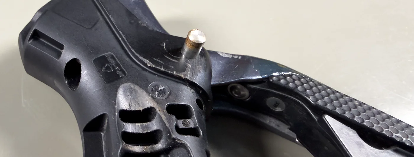
With the lever now separated from the shifter body, you can remove the switch using a Torx T5 driver. These screws are very small and can easily be damaged, so take care when removing them.
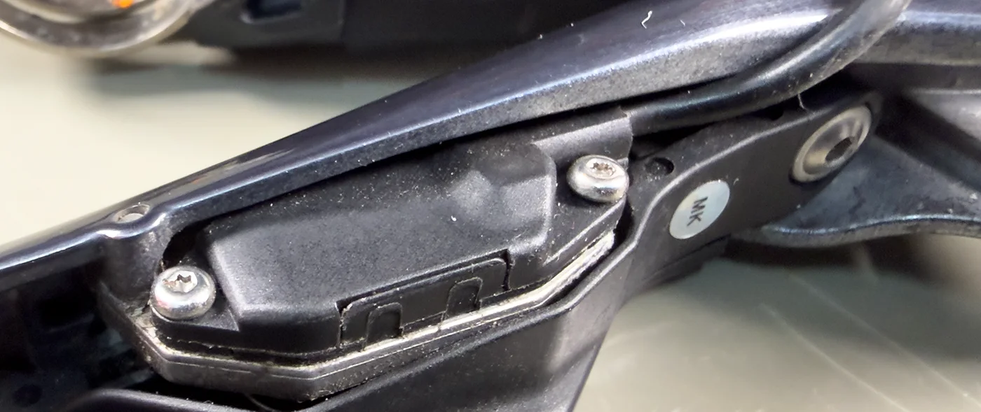
Under the switch block are two springs which return each of the switch blades.
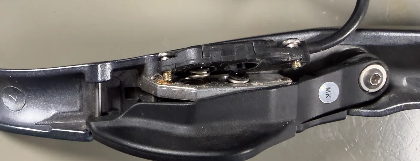
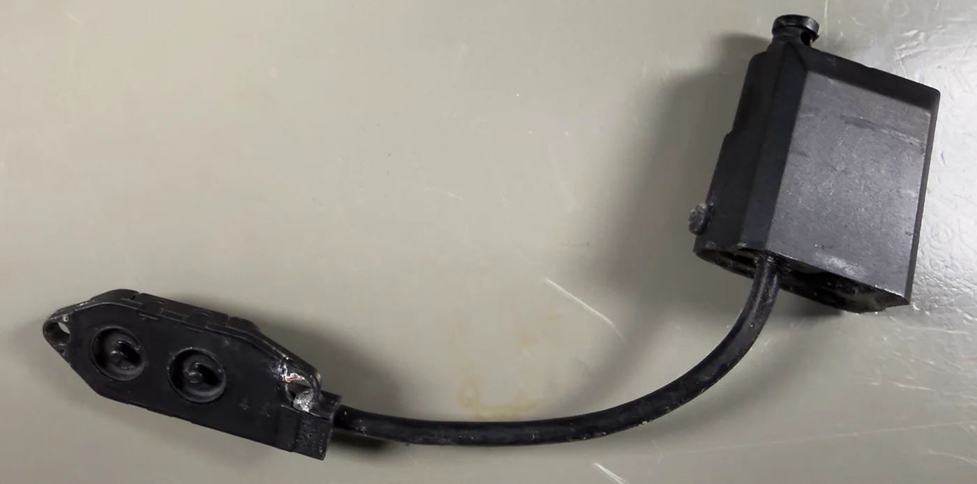
With the switch module removed, carefully unclip the Di2 connection block/module from the shifter body, and the switch and wire can be withdrawn from the shifter body.
Modifying the Shifter Switches and extending the cable
The Di2 controller box needs to be removed from the cable using wire cutters, and the cable needs to be extended to reach the middle of the handlebars.
Carefully remove the outer insulation on the switch wire which reveals three wires and a strainer cord.
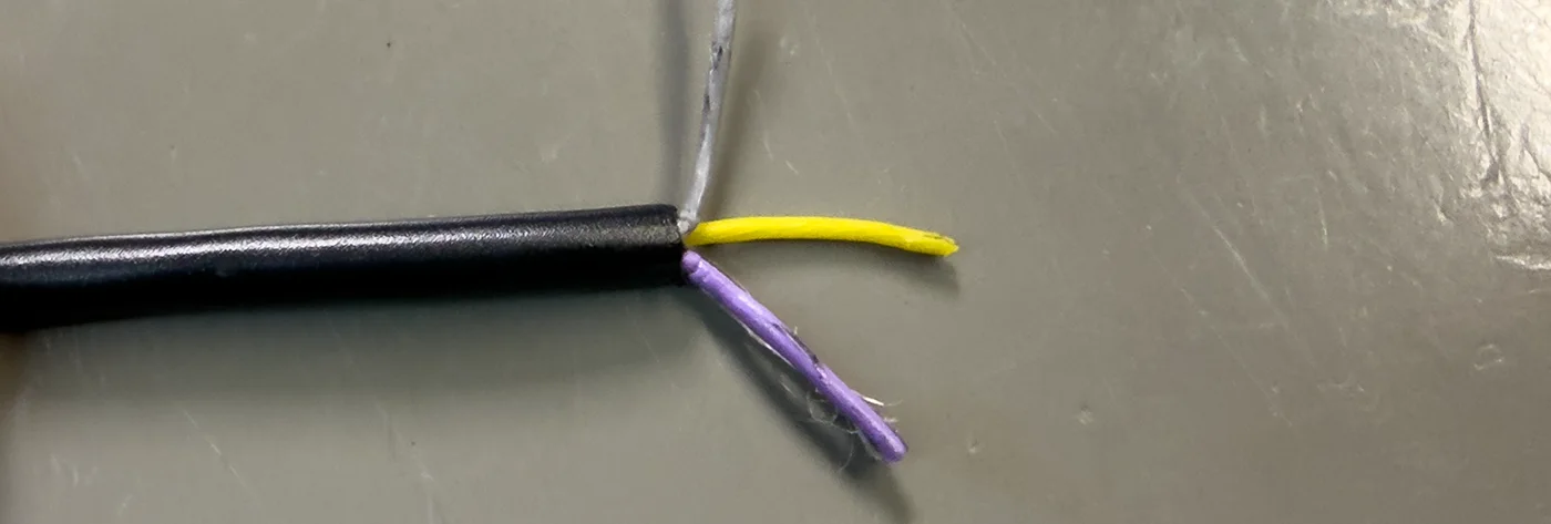
On my Di2 switch, the wires are connected as follows:
- Grey - Common
- Purple - Rear button
- Yellow - Front Button
Measure the length of cable required to route from the shifter to the centre of the handlebars when routed under the bar tape, and cut the 3.5mm Aux Cable as required.
Strip the ends of the aux cable, tin each of the inner ends and add short pieces of heat shrink to each of the inner cables and a larger piece to cover the outer cable and cover the soldered joints.

Solder the ground or braid to the grey wire.
Solder the purple and yellow wires to the other two cores on the cable, which connect to the centre pin and first ring on the 3.5mm stereo plug.
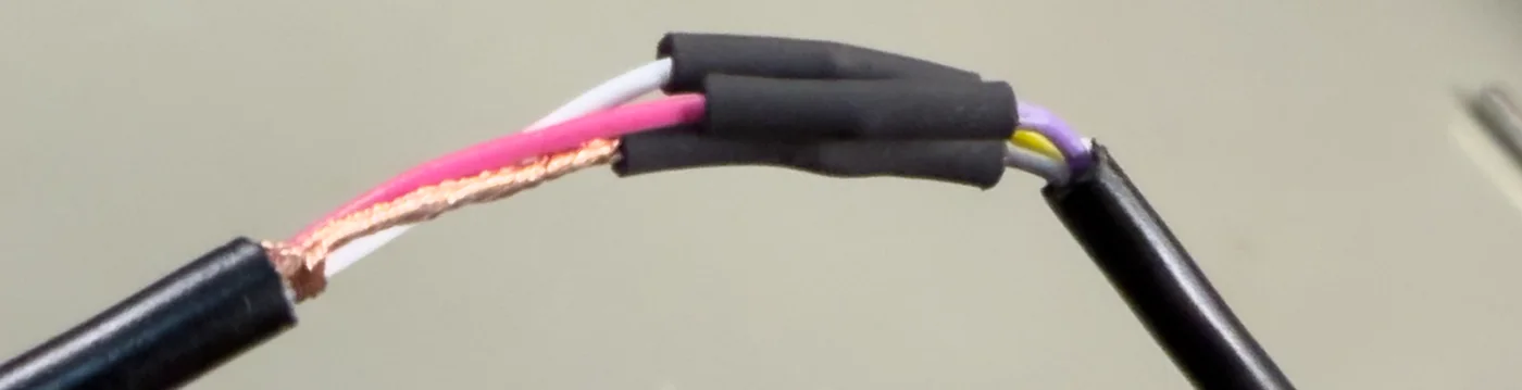
Slide the smaller heat shrink over the solder joints and gently heat to shrink to fit. Then slide the outer cover heat shrink over the joints and shrink to fit to protect everything.

The switch can now be fitted back to the brake lever blade and the cable through the shifter body.
Reattach the spring to the lever body and then reinsert the pivot pin. This will require tapping into place to fully seat the pin.
Install the circlip to attach the brake lever blade to the shifter body.
The cable can be routed via the slots intended for the Di2 wires and held in place using hot glue or epoxy resin. Ensure the brake lever can be squeezed without trapping the new wire.
The shifter's rubber hood can now be reinstalled, or this can be done after the shifter has been installed on the handlebars.
Creating the Y-splitter cable
With your Zwift Click buttons installed on your handlebars. Measuring the distance between each button and the centre of the handlebar where the 3.5mm stereo plug is located, you need to create a Y-cable with the 3.5mm stereo socket with wires going to each of the Zwift Click controllers.
Cut the twin-screened cable to the required length and then separate the cables at one end by approximately 40mm, ready to be connected to the socket.
Remove the outer insulation the same amount on both cables and twist the wire braids together to solder to the cable strain relief part of the connector, and the two inner wires need to be soldered to the two pins on the back of the connector.
Refit the cover.
At the other end of the cable, separate the two cables, leaving a few centimetres at the socket end and remove the outer insulation by approximately 12mm.
Twist the braid and make sure that all the copper strands are used, then strip approximately 1mm of the insulation from the centre wire and apply a small amount of solder to the wire and braid.
Repeat for the second wire.
Insert the 3.5mm plug into the socket.
Using a multimeter in continuity mode, connect the meter probes to the braid on one cable and the other probe to the centre wire and press each of the buttons on the Di2 shifter to check which shifter button is connected to each cable.
The button you wish to use for shifting up to a harder gear needs to be connected to the Zwift Click button with the plus button, and the button to shift down to an easier gear needs to connect to the Zwift Click with the minus button.
Zwift Click V2 modifications
Both Zwift Click controllers need to be modified to add wires to connect to the gear up and gear down buttons and to connect to your modified Di2 shifter buttons.
To avoid mixing up the circuit boards on the controllers, I recommend modifying the buttons separately.
On the base of each Zwift Click are four small cross-head screws, which remove the lower cover and give you access to the button cell inside.
Remove the four screws and carefully separate the two halves of the case. Remove the battery from the lower part, as you need to drill a hole in the plastic to pass the cable inside.
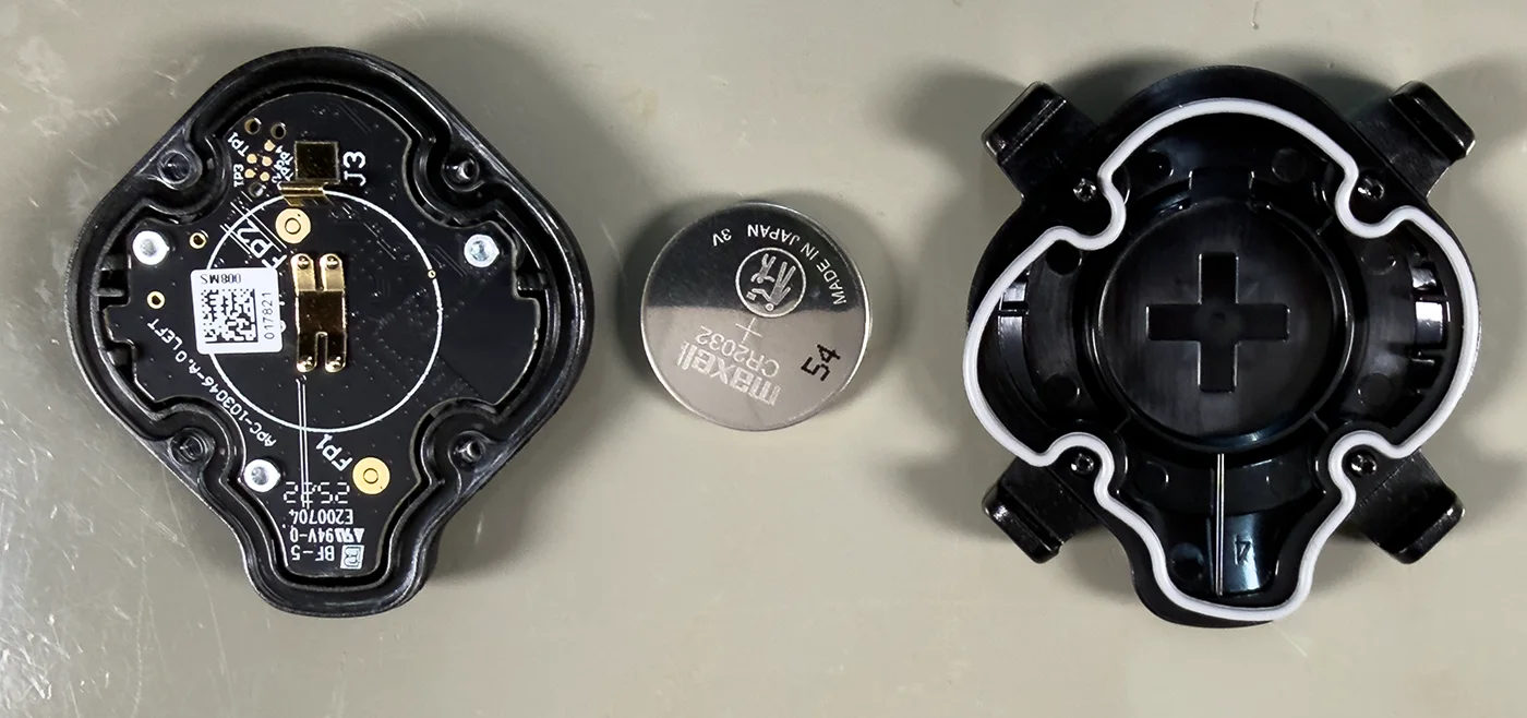
On the top cover, turn this upside down to show the circuit board side, where there are three small T5 torx screws which need to be removed.
With the screws removed, you can now remove the circuit board from the top part of the case.
Turning the circuit board over shows the five small buttons used to control Zwift.
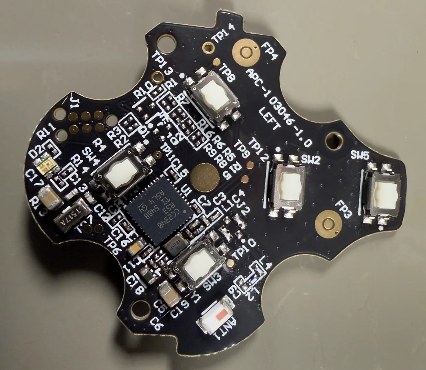
The controller uses a Texas Instruments CC2340R SimpleLink 2.4GHz Wireless MCU with a 48MHz Arm Cortex M0+ processor.
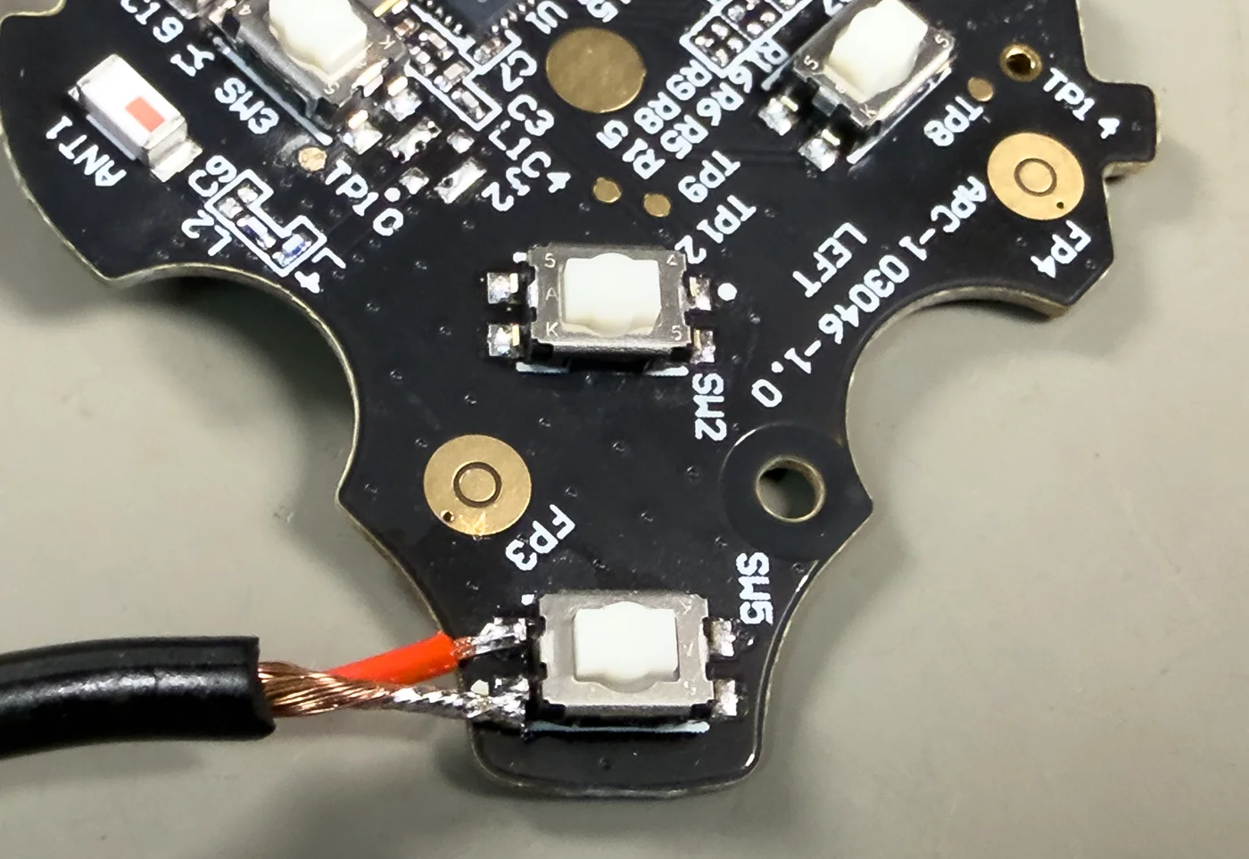
Using a 3mm drill, I created a hole on the lower left of the back of the case, below the gear up and down button location. The wire then needs to be passed through this hole, ready to be soldered to the circuit board's switch pins.
The photo below shows the correct location for the cable entry hole.

Pass the wire through the back of the case before soldering to the board.
The switches on the PCB have four small pins. Using the soldering iron, apply a small amount of solder to the left side pins of the switch marked SW5 and solder the wire braid to the pin nearest the bottom of the circuit board and the centre wire to the upper left pin.
Carefully fold the wires around the edge of the circuit board and reinstall them into the front of the case with the three Torx T5 screws.
Install the rubber gasket and battery, feed the wire through the back of the case and fit the rear cover back to the front panel.
You can now test the switch connection to the Di2 shifter, which should start the pairing process when pressed.
Repeat this for the second controller.
Installation onto the bike
Remove any bar tape on the side of the handlebar where the shifter is to be installed and mount the Di2 shifter onto your handlebar.
The wire needs to be routed under the bar tape to the middle of the handlebar, where it will be connected to the Zwift Click controller splitter cable.
Refit the shifter's rubber hood.
Install the Zwift Click controllers onto the handlebars and connect the 3.5mm stereo plug and socket.
You can now connect your bike trainer to Zwift and enjoy virtual shifting using both the Zwift Click controllers and your modified Shimano Di2 shifter.
The video below shows the shifters in operation.


Dave
Thank you that’s really informative
I am very tempted to try and replicate this.