Three years ago we designed a solar data logger based on a Raspberry Pi which monitored the solar heating and PV system in the house as well as measured the amount of energy we were using. This system has served us well but over time we have found a few small problems with the setup and a few extra things that we would like to add.
The old installation
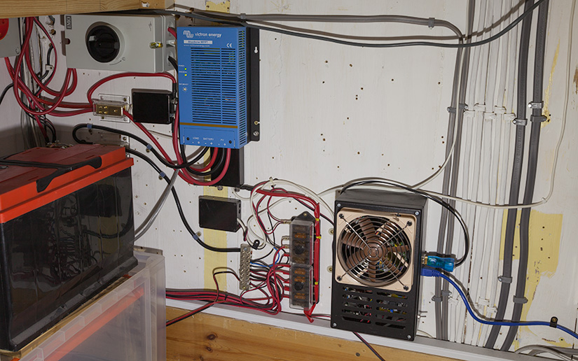
As the photo above shows the current system is a maze of cables joining the various parts together with separate current sensor boxes for the solar panels and batteries and distribution fuse boxes for the 12V power system that runs around the house. What we wanted was a single unified system that would take the bulk of the wiring and sensors and place them on a single circuit board. We also wanted to add extra communication systems for talking to wireless temperature sensors around the house and other systems that we are planning on adding in the near future.
One issue we found with the current system is the 100W solar panel that we have to keep the 12V batteries topped up is not big enough to run a Raspberry Pi 24 hours a day 365 days a year. For most of the year when it is sunny the panel keeps the batteries charged but in the winter when you get several weeks of dark overcast weather and short days the panel cannot keep up with the power being used by the Raspberry Pi and the two 160Ah batteries run out of energy. Several times throughout the winter we have to use a car battery charger to top up the batteries and stop the voltage from getting too low. The new system will use mains power to run the Raspberry Pi and all of the associated electronics and the 12V battery system will be used for the USB chargers and lighting which have low-voltage cut-out circuits built into each device.
The first stage of designing the new system was figuring out what we wanted it to do. The system will be designed around a Raspberry Pi model B+. The B+ has Ethernet and four USB sockets so we can connect the Raspberry Pi to our network and if we need to expand it in the future we can do so using USB adapters. We can also upgrade to the Raspberry Pi 2 if we need more power by simply unplugging the old Raspberry Pi and plugging in the new one.
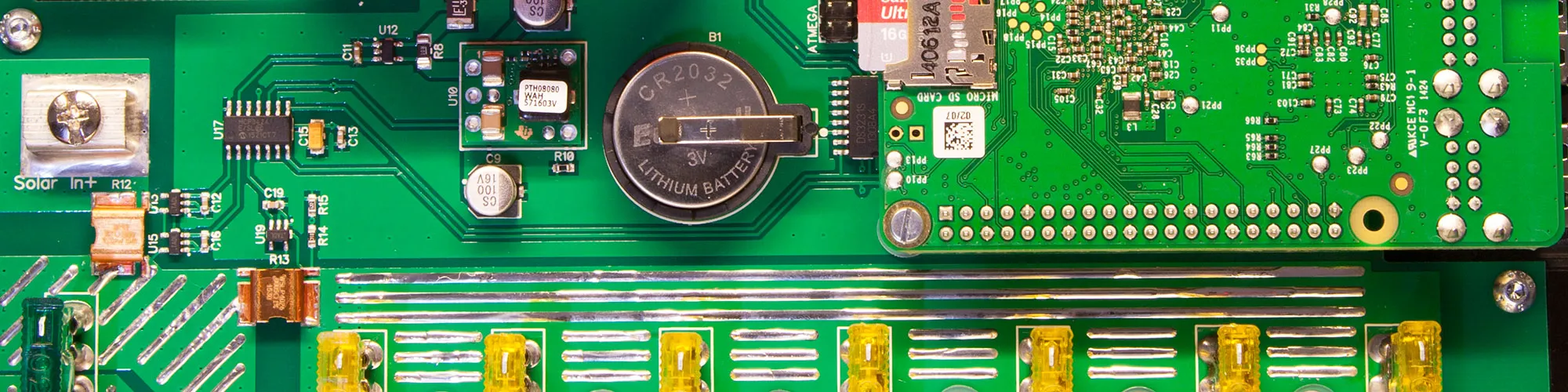
The main purpose of the system is to measure the battery voltage on the 12V batteries, the current coming from the solar panels and the current being used by the 12V circuit around the house. To measure the voltages and current we used a Microchip MCP3424 18-bit ADC. This is the same ADC that we use in the ADC Pi development boards that we make for the Raspberry Pi. We decided to base most of the circuit on parts we already use on our development boards mainly because we know they work well with the Raspberry Pi and we have a large stock of the chips and components so the build cost will be reduced.
To measure the voltage, we used a simple resistor voltage divider to drop the battery voltage down to a level that the ADC could manage which was ±2.048V. For the current measurement of the solar input and battery output, we decided to use 5mR shunt resistors connected to TS1100-100 current sense amplifiers. The TS1100 amplifies the input value by a factor of 100 so the 0.005R resistors will give us a voltage at the ADC of 2V for a current across the shunt of 40A. On the solar input, we used two of the current sense amplifiers configured to give us a differential output so we can measure the amount of current flowing back into the MPPT charge controller at night and see how much power it consumes, something we couldn’t do with the old system.
As the ADC we chose has four inputs and so far we had only used three we decided to add a 0.1R shunt and current sense amplifier across the 5V output for the mains power supply that powers the system so we can see how much power the Raspberry Pi and the other circuits are using.
The solar hot water system uses DS18S20 temperature sensors for measuring the temperature at the solar panel, the top of the hot water cylinder and the bottom return pipe. The DS18S20 uses a 1-Wire bus so to communicate with these sensors we used a DS2482S-100 1-Wire to I2C interface with a DS9503 ESD protection diode to protect against any voltage spikes on the bus. The I2C bus on the new circuit runs at 3.3V while the 1-Wire bus uses 5V so we added a level shifter using a FDC6301N double MOSFET. An RJ-12 socket at the top of the PCB connects the system to the 1-Wire bus around the house. This circuit is almost identical to our 1-Wire plus development board.
We added a DS3231 real-time clock to keep the time during power outages. This is probably not needed as the Raspberry Pi can get the current time from the internet but we had several of the chips from a sample order that I placed with Maxim several years ago so I decided to add it into the circuit anyway.
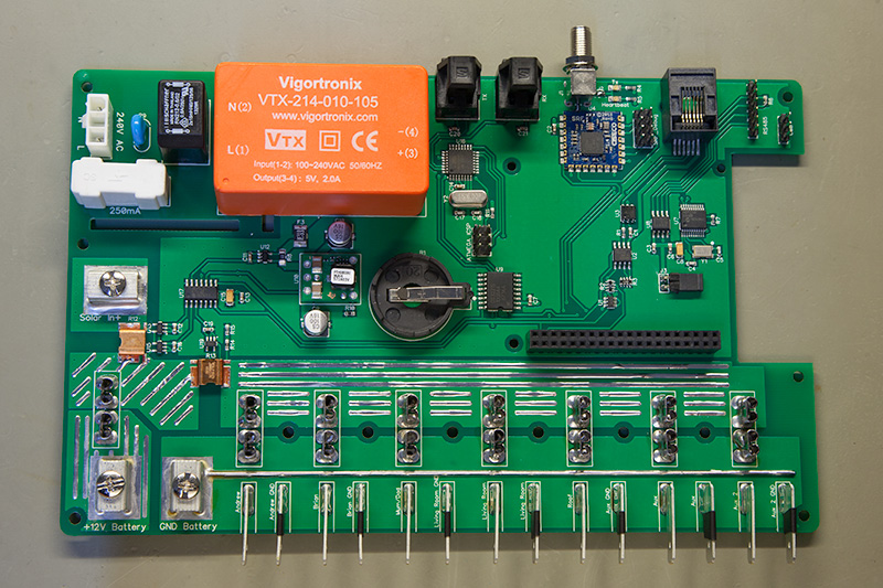
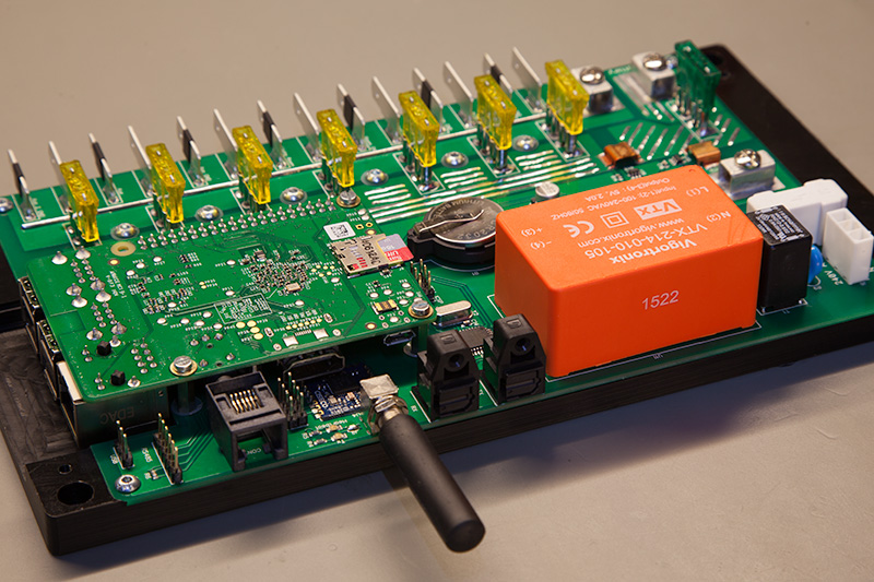
For measuring the temperature in each room of the house we initially looked at several options. We didn’t want to run another bunch of cables around the house so we would need to use wireless sensors. We did consider making some Bluetooth LE-based sensors but after experimenting with using Bluetooth LE dongles we found that the brick and limestone walls in the house do not work well with 2.4GHz. In the end, we decided to use a Ciseco SRF wireless model from wirelessthings.net. The SRF module uses the ISM bands (868 to 915 MHz) which pass through stone walls better than 2.4GHz. Wirelessthings.net also sell a range of wireless temperature sensors which we will place in each room of the house. The SRF module is a surface-mount PCB which can be soldered directly onto the main PCB. The antenna connects to the module from one of the pins through an SMA connector that was placed directly next to the module to cut down losses. The module runs at 3.3V and connects to the Raspberry Pi through the UART port. If the SRF module works well, then we will probably use the same system for other wireless devices in the future.
When we designed the new solar logging system we did plan on connecting it to our mains inverter through a fibre optic interface but as we found out in a previous blog post the inverter was too noisy for the fibre optic adapter to work so we had to abandon that idea. The solar logger still includes the circuitry to connect to the inverter which consists of the fibre optic transmitter and receiver connected to an ATMEGA328P microcontroller which would act as a buffer and I2C interface for the Raspberry Pi. While we won’t be using this circuit for the mains inverter we may use it in the future to connect to a weather station on the roof as the fibre optic interface will give good protection against lightning strikes.
We are designing several new devices that use an RS485 bus so an interface would be needed on the solar logger. The problem we faced was the RS485 interface needs a UART port and the Raspberry Pi only has one UART port which was already being used for the SRF wireless module. To get around this problem we used a Microchip MCP2200 USB to UART interface which turned one of the four USB ports on the Raspberry Pi into a UART port. An SN65HVD71 UART to RS485 converter translates the 3.3V UART signals into the differential voltages that are needed for the RS485 bus.
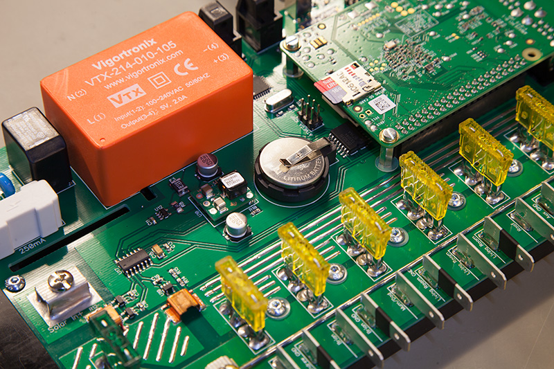
To power the system we used a 5V switch-mode module which connects to the 240V mains through a choke, MOV and fuse for circuit protection. The Raspberry Pi and 1-Wire bus use 5V while the rest of the circuits run at 3.3V so we used a PTH08080W DC-DC converter from Texas Instruments to drop the 5V down to 3.3V. A polyfuse was added on the output from the switch-mode supply so any faults or short circuits will blow the fuse instead of the power supply.
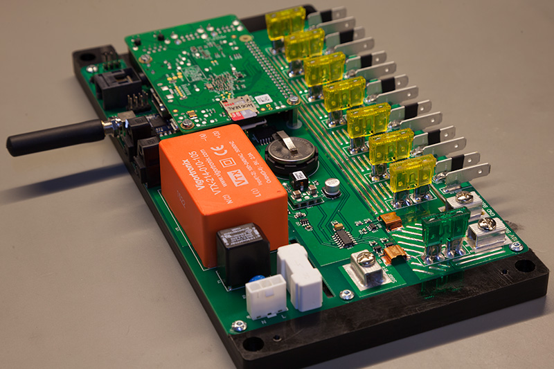
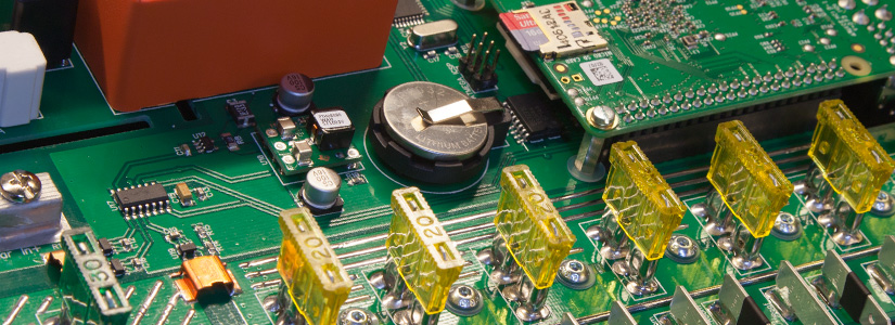
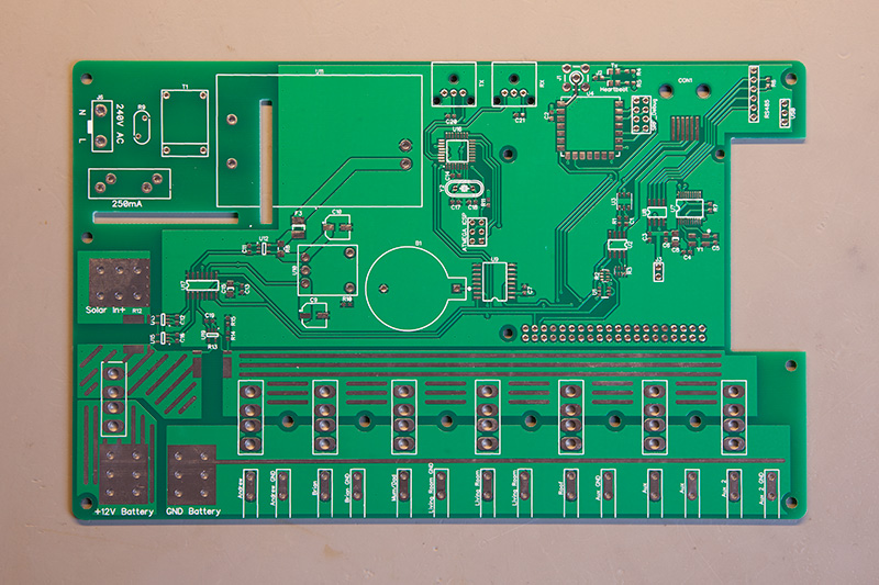
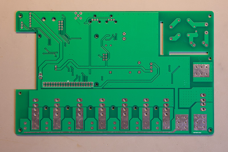
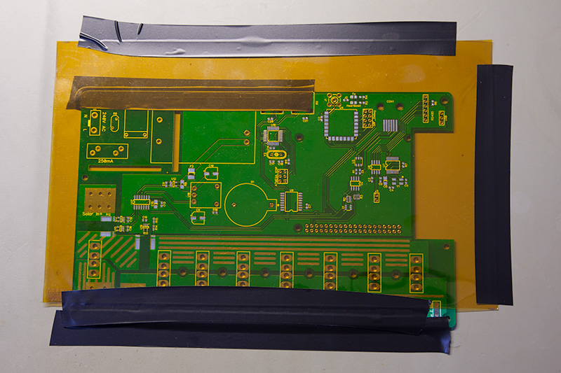
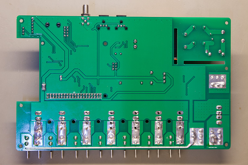
With the circuit designed the next stage was to design the PCB. The biggest challenge we faced was fitting everything onto a PCB small enough that we could make the case on our milling machine. Our mill can cut up to 25cm by 13cm so the PCB needed to be smaller than that. The biggest factors when designing the PCB were the size of the traces on the 12V line which would need to handle up to 40A plus the fuses on each of the distribution circuits, spade connectors for the outputs and screw terminal connectors for the battery inputs and solar panel input. Add on the size of the Raspberry Pi and the switch-mode power supply and space was going to be tight.
To reduce the size of the 40A traces we placed them on both sides of the PCB and used lots of vias to connect both sides together. 2-ounce copper traces were used for the PCB and lines of solder were also run along the top of the 12V trace to increase the current capacity. For the ground trace along the bottom edge of the PCB, we soldered a copper wire along the top and bottom sides to increase its current capacity. In reality, the system will most likely never need to draw more than 10A so the 40A traces are probably overkill but it is better to over-engineer than have problems with the traces overheating. Just to add a bit more protection a 30A fuse is used in the battery input so that will blow long before the traces do.
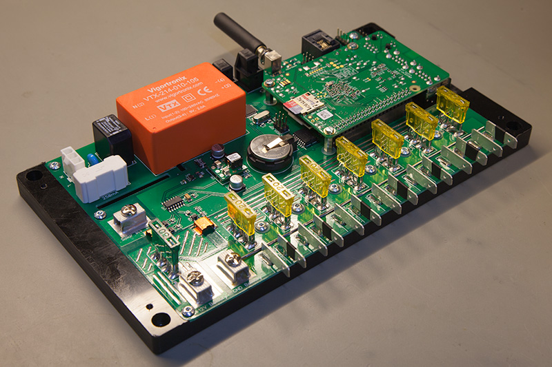
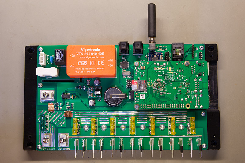
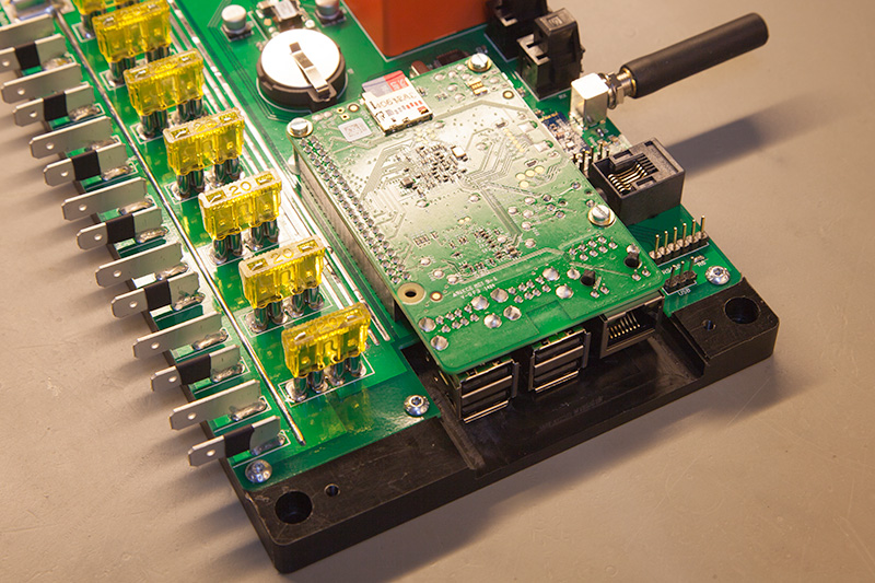
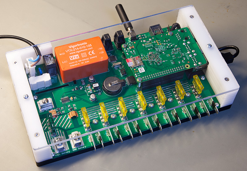
To fit the Raspberry Pi onto the board we decided to place it upside down over the PCB and plug it into a 40-pin connector on the board. Three mounting posts were added to keep it secure. This approach had the benefit that the space under the Raspberry Pi could be used for the RTC, 1-Wire interface and the USB to RS485 interface.
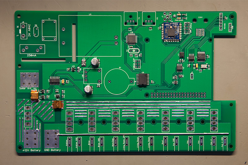
The mains power supply was placed in the top left corner and isolation slots were added in the PCB to stop the mains electricity from getting anywhere near the 12V rails. All of the 12V connectors were placed along the bottom of the board with the exception of the solar panel input which was placed on the left edge. This was done because the solar MPPT controller will be placed to the top left of the solar logger so the cable can be as short as possible.
All of the communication ports were placed along the top edge and the Raspberry Pi Ethernet and USB ports come out of the right side. The layout of all of the ports and connectors should mean that the cables come out of the PCB and head in the direction they are needed so the overall installation will be a lot tidier than the old setup. In the end, we managed to fit everything onto a PCB 20cm by 12.5cm.
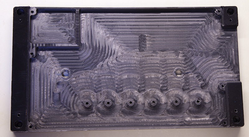
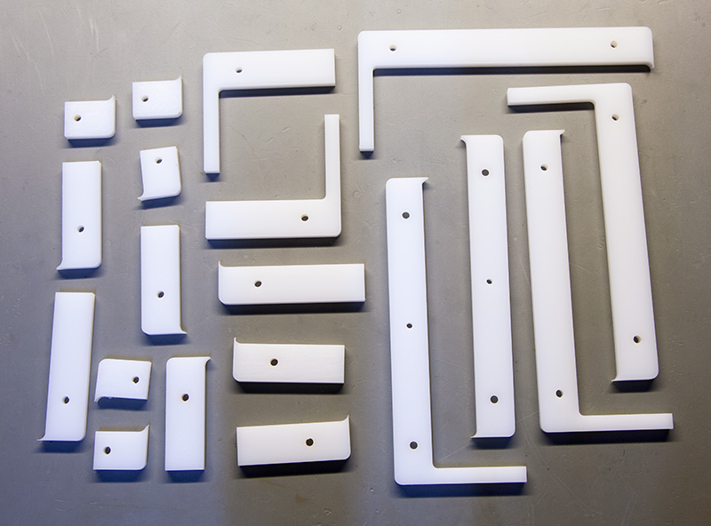
With the PCB built the last thing to do was make the case. We had some old sheets of Delrin and acrylic sheets left over from previous projects so a case was designed in Adobe Illustrator and cut on the mill. The base is machined out so the PCB bolts down in several places and the Raspberry Pi ports are recessed into the right side. The sides of the box are made up of six layers of acrylic cut to allow all of the connectors to be accessible and shield the 240V part of the circuit. The top and bottom of the case were left open to allow air to flow up through the Raspberry Pi keeping it cool. A clear lid was cut for the top and secured in place with two bolts.
Initial tests of the new system showed that everything was working as expected. The battery voltage and current shunts were calibrated using our Maynuo Electronic Load and we can get good accuracy down to around 1mA.
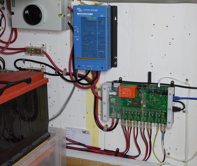
The old system was removed from the cupboard and the new one was installed in its place. The big bundle of wires now looks a lot more presentable and easier to manage and the next stage is to write all of the software which will control the new system.
The new installation
The PCB design files in DipTrace format, software and datasheets for the parts used can be downloaded from GitHub at https://github.com/briandorey/RaspberryPiSolarLoggerV2
We are also working on upgrades to our online data logging site on home.briandorey.com to use the data from the new logging system.


Mukundan
Nice , Super work !!!
Nur Faizin
intend to research related to solar panel monitoring systems. can i order, monitoring solar radiation, temperature, panel power (voltage and current) with Resberry pi? thanks
nur
Have you considered using an external database or networked storage to mitigate this?
Best Regrads
nur