
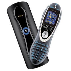
 After looking for more items around the house which could be charged from the new solar system, we decided to try converting the Logitech Harmony 885 remote control chargers to run from 12 volts.
The Logitech charger runs at 8 volts and uses around 0.4 amps when charging the remote controls.
Using an LM2825N-ADJ Integrated Power Supply 1A DC-DC Converter from National Semiconductor, 2 surface mount resistors and 1 surface mount capacitor we made a small PCB to fit inside the base of the charger which would accept an input voltage from 9V to 40V.
The remote was modified with the addition of a small magnet in the base and in the charger a reed switch was added to allow the remote to automatically turn on the charger when it was placed in the charging cradle. This greatly reduces the energy these chargers normally use as they are designed to run from a plug-in mains adaptor which is normally left connected 24/7.
Stage One - Adding the magnet to the remote control unit.
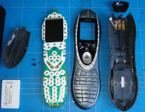
The above photo shows the Logitech remote after removing the various components.
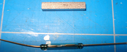
The above photo shows the 18mm long magnet fitted into the base of the remote control.
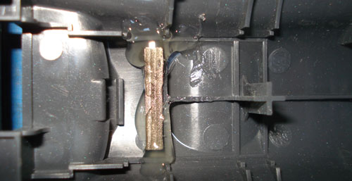
The above photo shows a magnet fitted in the remote next to the battery compartment lid catch.
Stage Two - Modifying the charging cradle
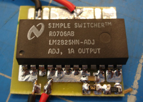
The above photo shows the DC-DC converter fitted to a basic printed circuit board.
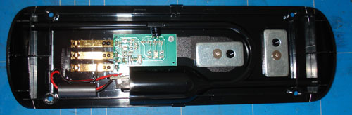
The above photo shows the inside of the charging base prior to modification.
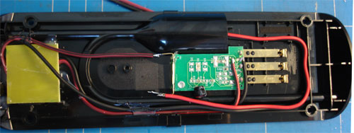
The above photo shows the charging base with the reed switch fitted on the end of the existing PCB and the new DC-DC converter fitted into a new hole in the base of the case.
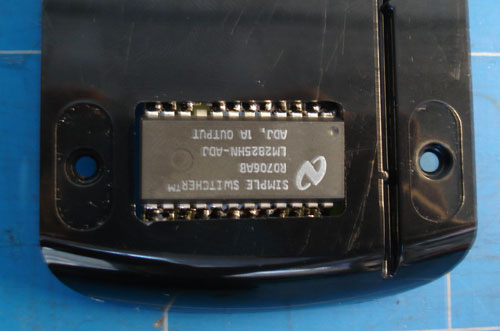
The above photo shows the base of the charger with the DC-DC converter in the new cutout.
New rubber feet were fitted to allow extra clearance to the charger converter when sat on the table.


Comments