For several years, we have been using a Raspberry Pi as a small Linux server for monitoring our solar heating system and power usage throughout the house. While the Raspberry Pi has been perfectly suitable for the tasks it has been given, we needed something a bit more robust for some of our other projects.
Asus recently released the Tinker Board, an ARM-based computer in the same format as the Raspberry Pi but using a more powerful Rockchip RK3288 CPU. It has gigabit ethernet and separate controllers for the ethernet and USB, so the network performance should be faster than the Raspberry Pi. We ordered a Tinker Board when it was first released in the UK in February 2017 to use it to test compatibility with the Raspberry Pi development boards we make and sell, but after using it for a while, we decided it might make an excellent small Linux server to run alongside our existing Raspberry Pi server.
The server would be used mainly for hosting several websites, including the Partkeepr inventory manager, which we use to keep a database of the thousands of electronic components we have collected over the years. As well as a web server, we also need a local GIT server to store our development work's backups. A DNS server for adblocking on our computers and tablets would also be helpful. We had a spare 120GB SSD with a USB to SATA adapter that would be suitable for file and database storage, so we decided to use a 32GB SD card for the OS installation and the SSD as the storage drive.
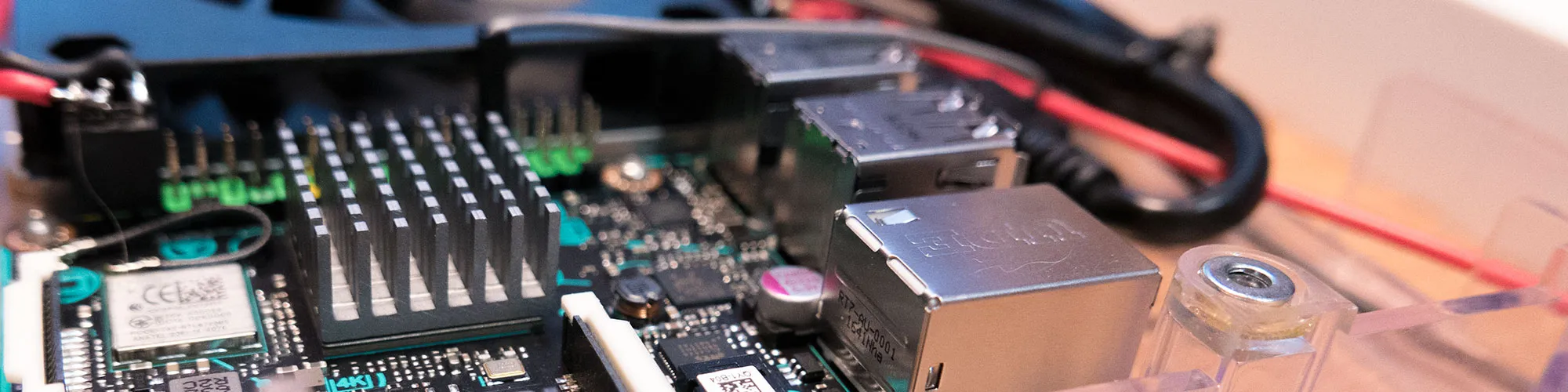
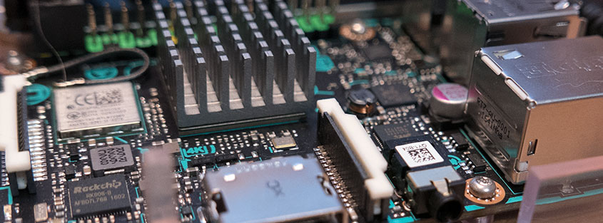
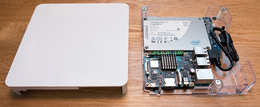
We used a WD PiDrive 6x6 enclosure from Western Digital to mount the Tinker Board and the SSD together. The PiDrive enclosure has space to mount the Tinker Board and SSD alongside each other, with a short USB cable to connect them. We had to make small modifications to the enclosure to make everything fit. The PiDrive enclosure is designed to be used with Western Digital's USB drives which have the USB connector in a different place than our SSD, so we had to remove a piece of curved plastic which would typically be used for cable routing. We added slots that we cut into the side of the lid to add some extra airflow as the Tinker Board runs hotter than a Raspberry Pi. Western Digital supplied three magnets and washers to join the lid to the enclosure, but the kit did not include any way of sticking the magnets and washers to the plastic, so we had to use some epoxy resin to glue everything in place. Two holes were drilled in the base to mount the enclosure vertically on a wall next to our network switch.
The case with the SDD and Asus Tinker Board fitted with SATA to USB adapter.
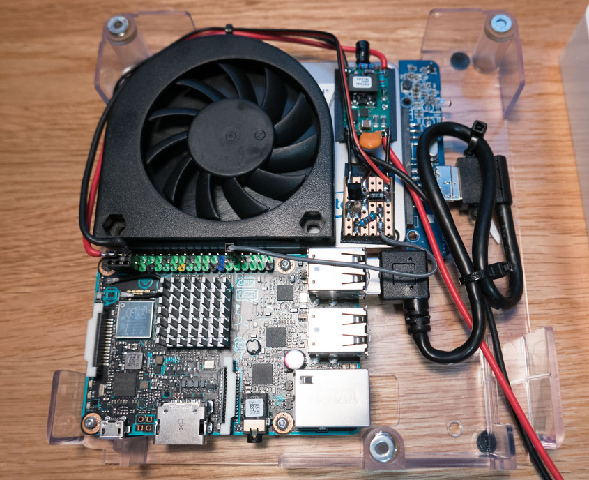
The server will be powered through our solar monitoring system, which has several 12V outputs. This way, we can monitor the amount of current the Tinker Board uses. The Tinker Board with the external SSD uses between 500mA and 1300mA depending on the CPU load, so we needed a small switching power supply to drop the 12V down to 5V. A PTN78060 3A regulator from Texas Instruments was salvaged from our old Pick and Place machine controller, and a sticky pad was used to fit it to the top of the SSD.
With the hardware complete, the next stage was to install Linux onto the SD card and format the SSD. Asus provides a version of Debian Linux on their support website, but at the time of writing, the rest of their support is very limited, with just a couple of FAQs and some libraries for setting up the GPIO pins. As the Tinker Board would be used as a headless server, there was little point in having a GUI running in the background, using up memory and resources. Hence, the first job was to remove X.org and the other associated GUI libraries. Webmin was installed so the server could be remotely administered through a web browser, and samba was set up so our Windows machines could access the system. The SSD was formatted and mounted as a folder in the root.
Next, Apache, PHP and MySQL were installed and configured to use the SSD as the database and web folder, and PartKeepr was set up. The DNS and Git servers will be installed later.
Keeping It Cool
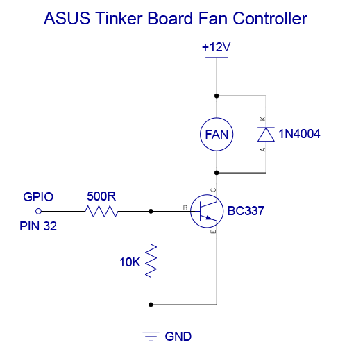
A few basic stress tests were performed to see how well the Tinker Board coped with high CPU loads, and it quickly became apparent that a fan would be needed as after a minute of 100% usage, the CPU would rise to 75°C and begin throttling. A 12V 55mm radial fan was found in our box of PC parts. It was originally designed to be fitted in a PCI slot on the back of a computer, but with a few modifications, it was fitted on top of the SSD, pointing at the CPU heatsink. A cutout was made on the plastic lid using our CNC mill to allow airflow into the fan, and a simple transistor-based control circuit was built onto some stripboard to control the fan using PWM from a GPIO pin.
To manage the fan speed, we wrote a simple program which gets the CPU temperature from /sys/class/thermal/thermal_zone1/temp and uses that to set the fan speed by adjusting the PWM output. According to ASUS, the PWM functions were not enabled on the version of Linux we were using, but their GPIO C API, available on their support website, included an example for controlling the PWM pin using WiringPi, so we tried modifying the example and found that it worked. The code and schematic for the fan controller can be found on our GitHub account.
With the fan fitted, we tried running the CPU at 100% load and found that even with the fan only running at 50%, the temperature would not rise above 55°C and with no load, the fan would stay off with a CPU temperature of between 35°C and 40°C.
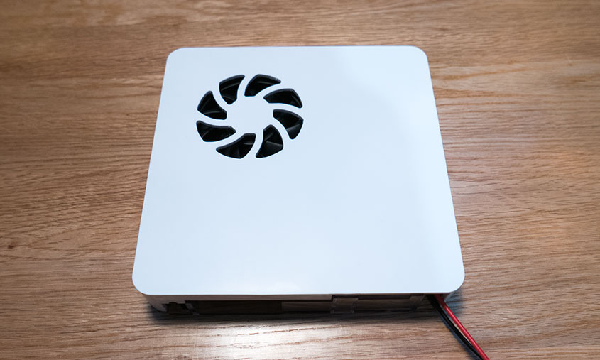
Case with SSD, Fan, Power supply, fan controller and Asus Tinker Board.
The completed case with fan cutout.
Speed Tests
A benchmark was run using sysbench to compare the performance of the Tinker Board against a Raspberry Pi 3. As both systems use quad-core CPUs, a 4-thread test was run with the following command:
sysbench --test=cpu --num-threads=4 --cpu-max-prime=20000 run
The results for the Asus Tinker Board are as follows:
Maximum prime number checked in CPU test: 20000
| Test execution summary: | |
| Total time: | 82.2044s |
| total number of events: | 10000 |
| total time taken by event execution: | 328.7541 |
| per-request statistics: | |
| Min: | 32.63ms |
| avg: | 32.88ms |
| max: | 72.21ms |
| approx. 95 percentile: | 33.41ms |
| Threads fairness: | |
| events (avg/stddev): | 2500.0000/26.05 |
| Execution time (avg/stddev): | 82.1885/0.01 |
The Raspberry Pi 3 gave the following results:
| Test execution summary: | |
| Total time: | 122.8869s |
| Total number of events: | 10000 |
| Total time taken by event execution: | 491.4391 |
| Per-request statistics: | |
| Min: | 47.69ms |
| avg: | 49.14ms |
| max: | 115.54ms |
| approx. 95 percentile: | 47.94ms |
| Threads fairness: | |
| events (avg/stddev): | 2500.0000/4.06 |
| Execution time (avg/stddev): | 122.8598/0.02 |
As you can see from the results, the Tinker Board is approximately 30% faster than the Raspberry Pi 3. We did not try a GPU benchmark, as the tasks we are running on the server will not make use of the GPU.
With the hardware and software ready, we installed the server in the cupboard alongside the wireless router and network switch.


Jochum
Nice build!
Could you tell me how tall the fan you used is (and if there is room for a taller one)?
J
Brian
It was one of these https://www.ebay.co.uk/itm/System-PCI-Slot-Blower-CPU-Case-DC-Cooling-Fan-12v-4pin-Cooler-For-PC-LaptopFE/332812337367?epid=27022967747&hash=item4d7d2940d7:g:nnIAAOSwk1NbW9-6
I am not sure of the height as I don't have access to the box at the moment as it is being used by someone else.
Adam Downer
Nice. Am so grateful for sharing this with me. Definitely going be very helpful in our build. Thanks and regards to the team. Cheers.
Brad
This is great! I was inspired to go get a Tinker Board. However, I'm having trouble getting Apache onto it. How did you go about that step? Did you use a copy of XAMPP or LAMPP, manual install from Apache Friends or self compile?
Brian
It was installed using sudo apt-get install apache2
Brad
Thank you! I was over thinking it. All is well.
Shoaib
Hi, Thank for sharing your experience. I am trying to create a server for my websites but I don't know how to create a server. After reading your article, I kinda understand how to do it but I am stuck how to use my tinker remotely. Would you mind me sharing that how to do it? I saw you have used samba for file sharing. What was the config for that?
Brian
Shoaib, We used SSH to login to the server to manage it. I don't have the box running at the moment but we used the default samba config for the shares.
kevin walker
Hi, could you tell me if pins 1 3 5 are connected on the tinker board it seems so in the photo or is the connection a blank to prevent shorting to pins 2 4 6, if they are why and where are they connected to. nice build though Im having to adapt some of the hardware but that's what its all about
Brian
kevin, Pins 2 and 4 are linked as the 5V output and pin 6 is the Ground connection to power the board and the SSD
kevin
ok thanks for the reply I had seen that the pins 2 and 4 were connected it was pins 1 3 and 5 that Im interested in ie: the 3.3v i2c1-sda and i2c1-scl pins just wanted to know if I need to connect them
Brian
kevin, I didn't connect anything to pins 1, 3 and 5, I only used a 2x3 pin head as it was one i already had available.
kevin
ok thanks for the help,
Thomas
Could you tell me what USB to SATA adapter you used, and whether you had to disassemble it at all to make it fit in the case. Most of the ones I'm finding have large plastic housings around the SATA connector, in the pictures it looks like yours is just a board with no housing.
Brian
Thomas, the USB-SATA adapter was from a 2.5" usb enclosure, I don't remember the brand we used but it was one of the cheaper models which cost less than £15.
Guillermo
Hi Brian, It is a really nice project. Thank you for sharing. Could you please tell me what is the performance of the mysql?, How many transaction do you do at day?, How about the write and read performance for the mysql?. Thank you.
Brian
Guillermo, I am sorry but I don't know the performance of the MySQL instance. We only used the system to read data and so it wasn't getting many writes to the database. We are not using the Tinker board now as we have changed to an Intel-based system.
rhys tippings
What wonderfully consise artificial, thank you.