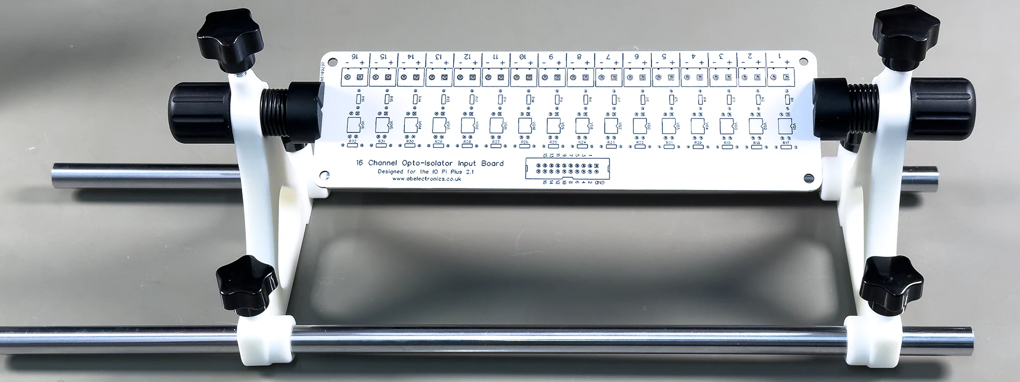
When assembling circuit boards, the ability to rotate the board easily makes soldering, particularly for through-hole components, far more straightforward. Commercial adjustable PCB holders are available in a wide range of shapes and sizes, from low-cost plastic models to larger, more expensive metal assembly jigs.
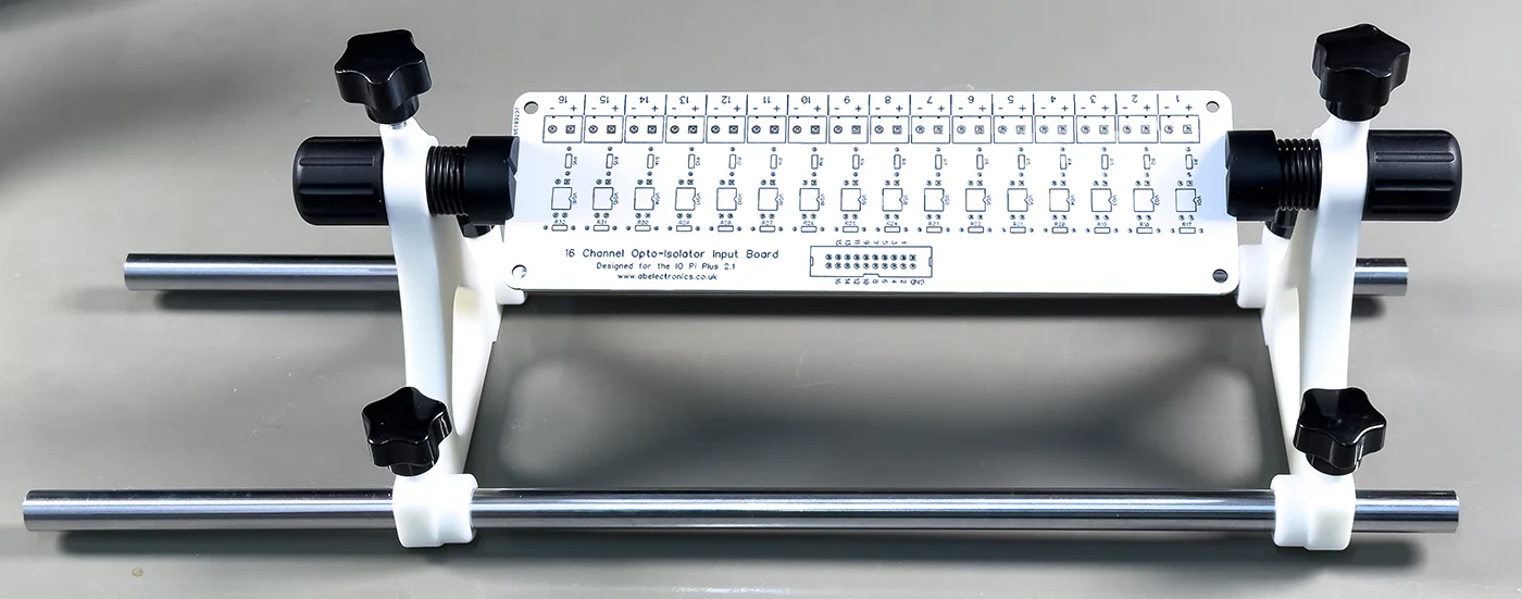
One of our future planned projects will involve PCBs up to 30 cm long and use a mixture of surface-mount and through-hole components, we decided to design and build an adjustable-length circuit board holder to simplify assembly.
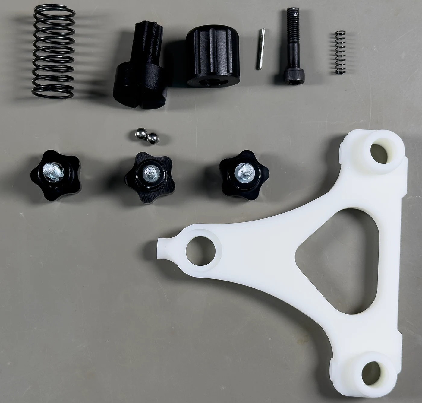
The holder is constructed from a combination of 3D-printed parts and hardware components supplied by JLC3DP.
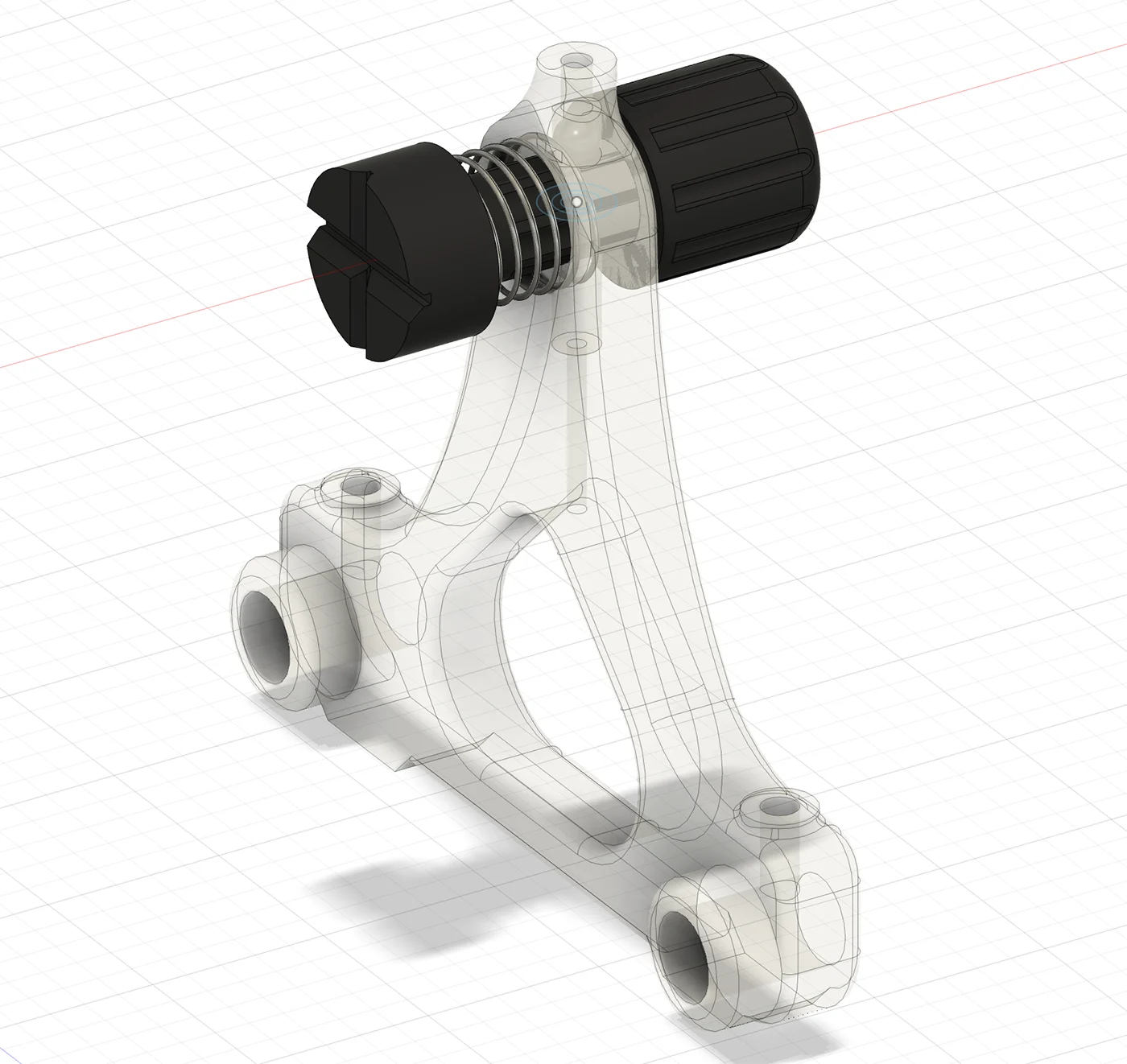
Design Overview
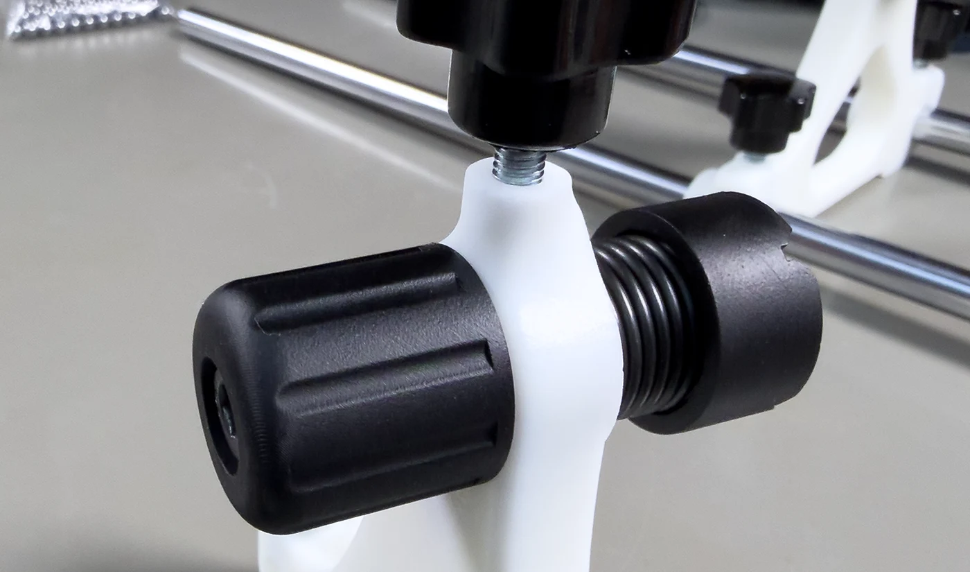
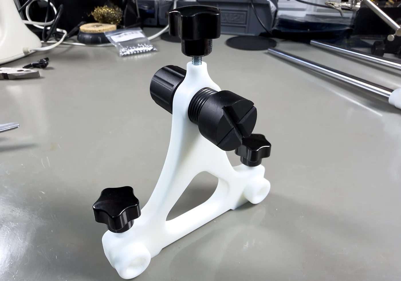
The design incorporates a rotating mounting shaft with indexed indents that lock the rotation at 45-degree intervals. A spring applies pressure to a ball bearing, which engages with each indent to provide positive positioning.
Knurled threaded knobs are used to secure the sliding ends onto the metal guide rods, with an additional knob fitted on the top to lock the PCB’s rotational position.
Horizontal clamping pressure is applied from each end by means of sliding rotating shafts and strong compression springs.
Hardware Parts
| Item | Part ID | Quantity | Link |
|---|---|---|---|
| 6mm Ball Bearings | 4 | Amazon | |
| Linear Rod | 12mm x 450mm | 2 | Amazon |
| Five Star Stud Knob | DBTJ-D-D25-M6-L15 | 4 | jlcmc |
| Five Star Stud Knob | DBTJ-D-D25-M5-L10 | 2 | jlcmc |
| Compression Spring Diameter 5mm Length 20mm | ATJQ-D5-L20 | 2 | jlcmc |
| Compression Spring Diameter 20mm Length 40mm | ATJQ-D20-L40 | 2 | jlcmc |
| Hex Socket Screw M6 x 40mm | EDLA-J9-M6-L40 | 2 | jlcmc |
| Positioning pin Straight rod h7 - Diameter 2mm Length 20mm | FDWN-S1-D2-L20 | 2 | jlcmc |
3D Printed Parts
These parts were ordered from jlc3dp.com. The 3D models can be downloaded from GitHub at github.com/briandorey/adjustable-pcb-holder
| Item | 3D Technology | Material | Colour | Surface Finish | Quantity |
|---|---|---|---|---|---|
| 3D Printed Ends | SLA(Resin) | 9600 Resin | Matte White | Sanding-General Sanding | 2 |
| 3D Printed PCB Mount and Knob | SLA(Resin) | JLC Black Resin | Black | Sanding-General Sanding | 2 |
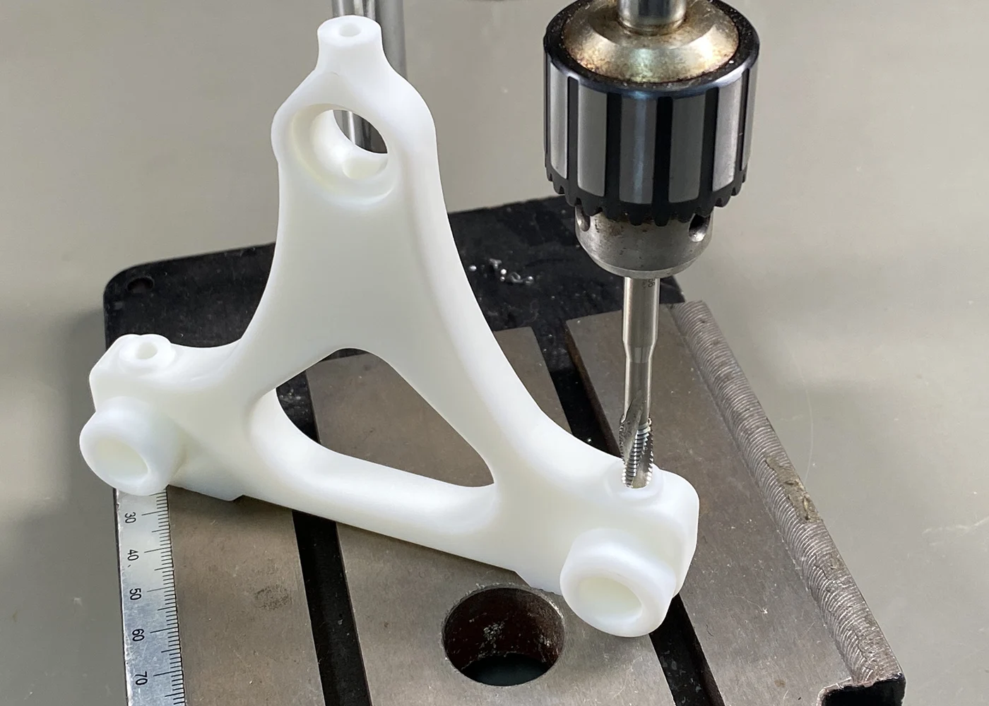
Assembly Instructions
Threading the Clamps
Using an M6 tap, cut threads in the inner clamps and on both sides of each end piece for the rail-clamping handles.
Rotation Lock Thread
Using an M5 tap, create a threaded hole on the top of one side to accept the rotation-locking handle.
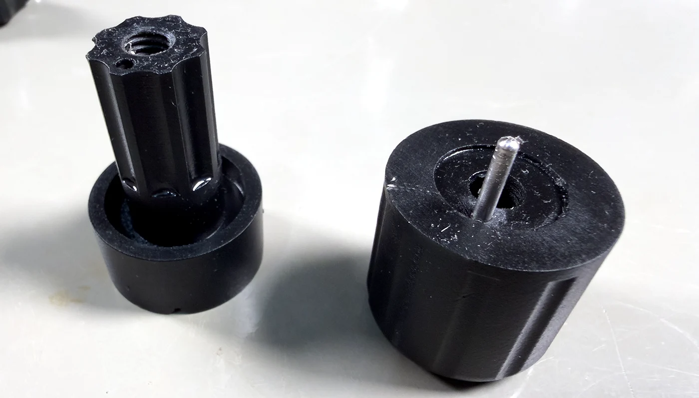
Preparing the Rotating PCB Clamps
Using an M6 tap, cut threads on the inner sections of the PCB clamping mounts.
Press the metal pin into one half of each clamp.
This assists alignment during assembly and prevents the two halves from twisting when bolted together.
Installing the Upper Bearing
Press a 6 mm bearing into the upper threaded hole, then install the handle used to apply pressure and lock the rotation when required.
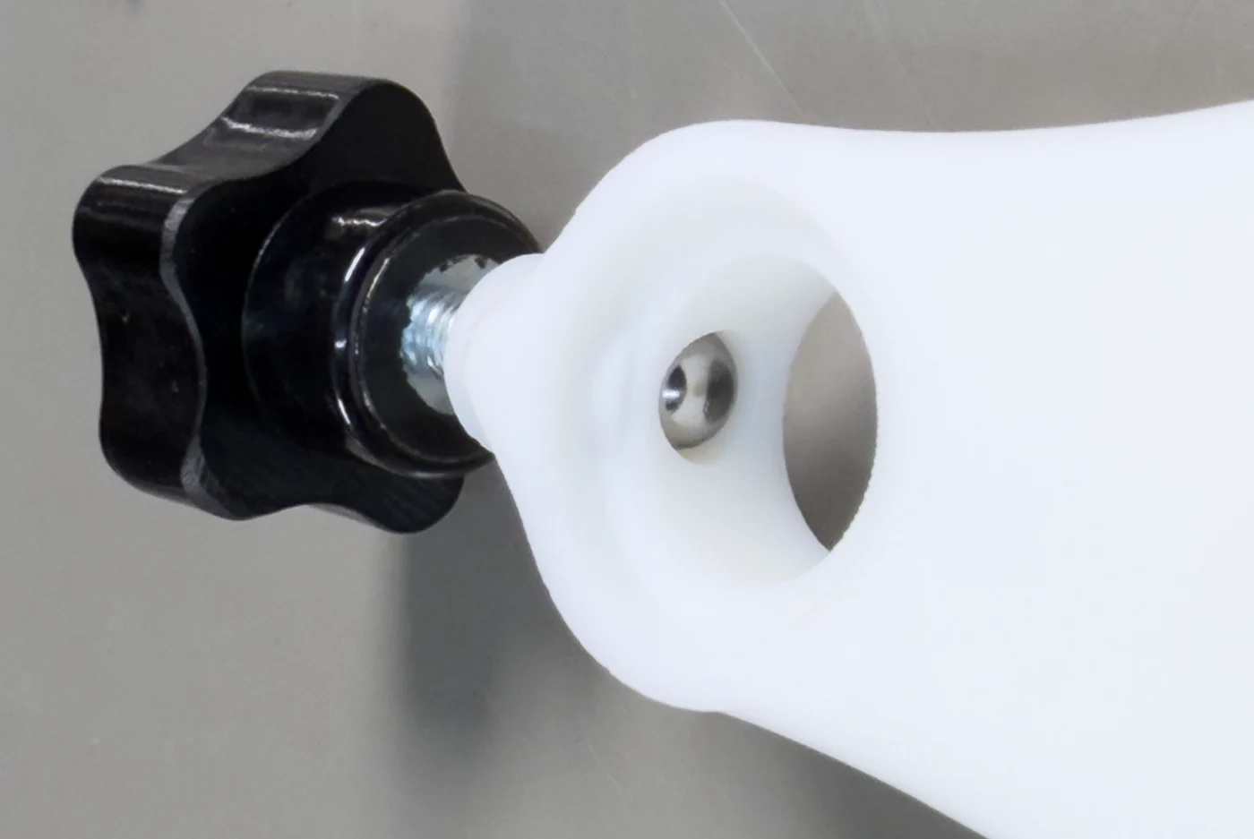
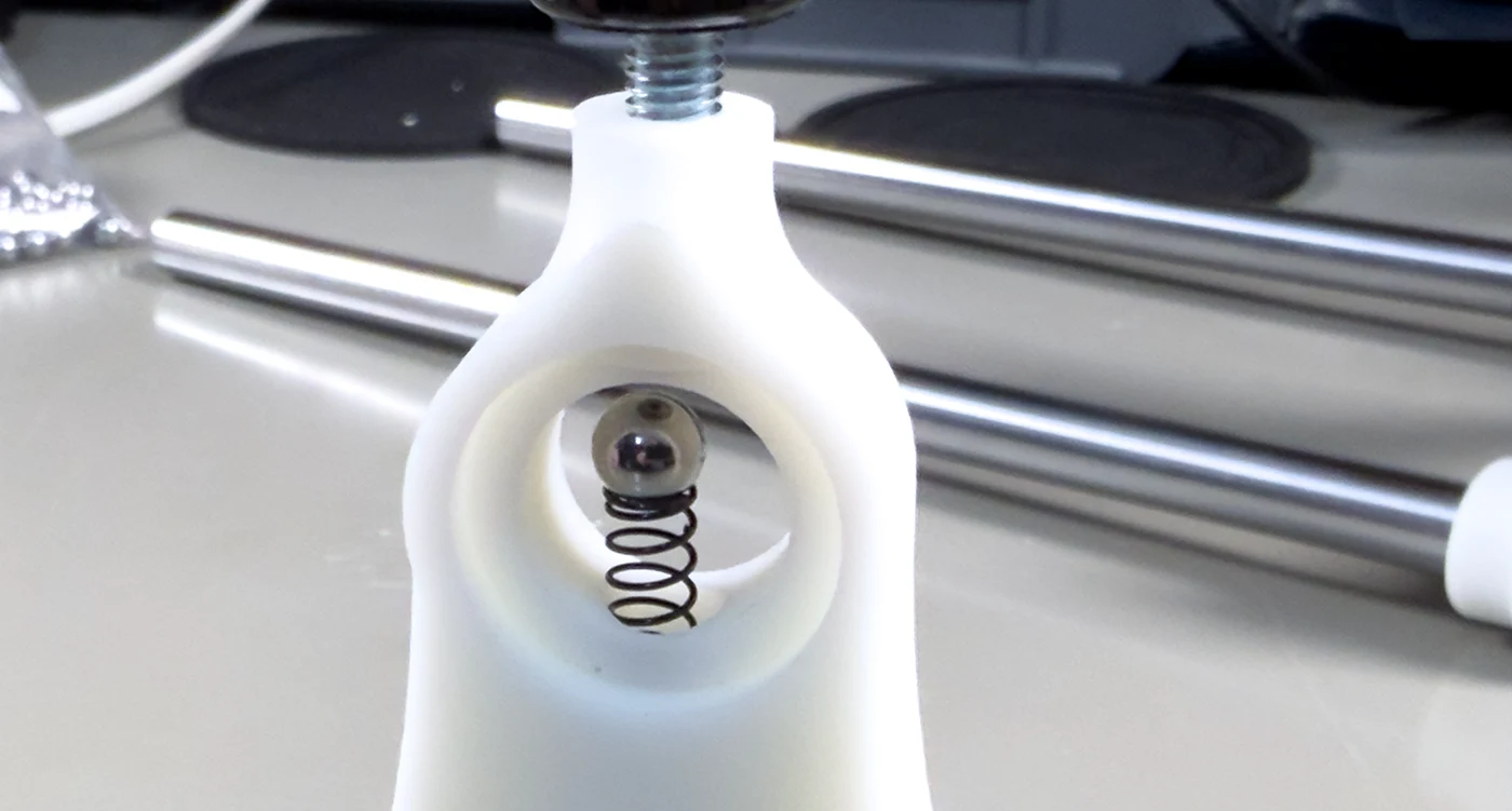
Fitting the Detent Mechanism
Insert the small spring into the lower side of the rotation hole and place the ball bearing on top. This provides resistance and indexing when rotating the PCB clamps.
Note: This must be installed at the same time as fitting the inner section of each clamp.
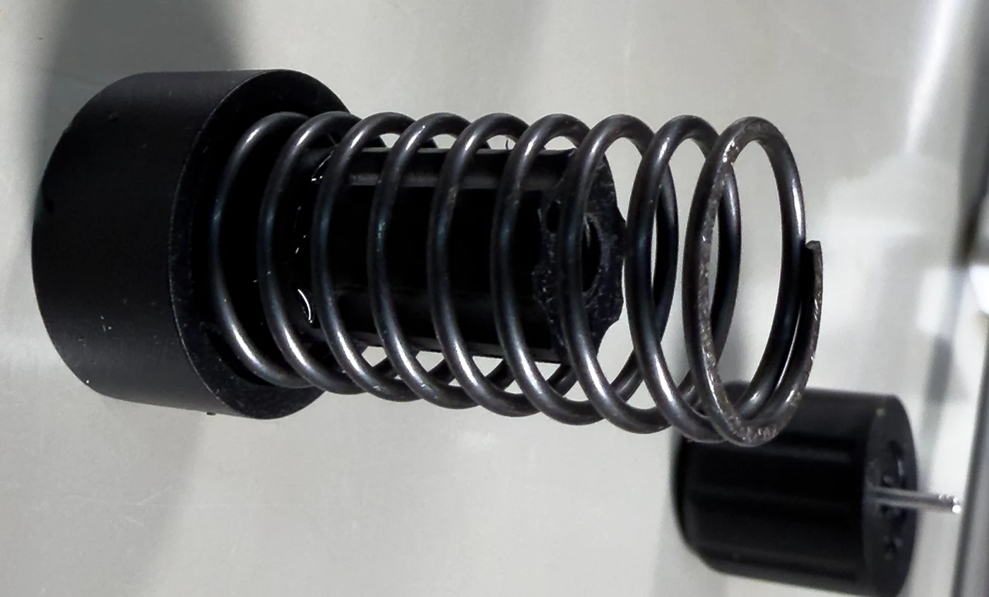
Install Pressure Spring
The pressure spring is installed onto the PCB side of each of the rotating PCB clamps.
Install Clamps into End Plates
Install the rotating PCB clamp into the ends of the mounts. The detent spring will need to be compressed to allow the inner clamp sections to be fitted, after which the outer handle can be secured using the M6 bolt.
The bolts may need to be shortened slightly to achieve a proper fit. A small amount of silicone grease may be applied to the rotating surfaces to ensure smooth movement within the end plates.
Install bearing rails
Once the end plates have been assembled, they can be installed onto the bearing rails, completing the build.
Depending on the quality of your 3D printer, you may need a 12mm reamer to bring holes to the correct diameter.


Comments