
Following the 4th Apple, iPad charger failing and not wanting to spend even more money with Apple to replace them we decided to try to make 12v powered chargers to make use of the excess PV power we now have during the daytime to charge the iPads and other devices which charge via USB.
I have a couple of ready-made USB car chargers but these will not charge the iPad due to the iPad needing a control voltage on both of the data pins which most commercial 12V chargers don’t seem to supply.
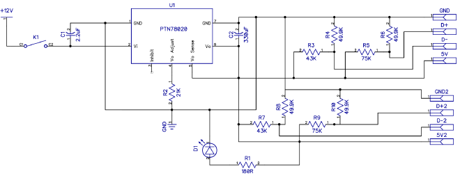
The circuit schematic (click for PDF) shows the new charging circuit diagram which uses a Texas Instruments PTN78020 6-A, Wide-input adjustable switching regulator to bring the input voltage down to 5V and then voltage dividers to supply the data lines with the correct voltage.
Testing a working iPad charger gave the following voltages:
USB Pin 1: 5V
USB Pin D- : 2.75V
USB Pin D+: 2.065V
From these, we calculated the nearest resistor values to create the voltage designers and then built 3 chargers for use around the house.
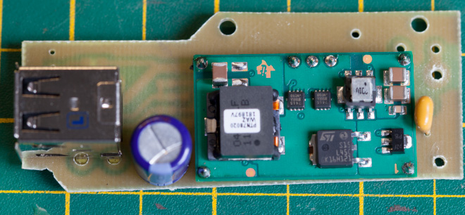
The completed charger circuit top view shows power regulator and smoothing caps.
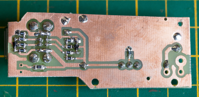
The completed charger circuit base view showing voltage dividers.
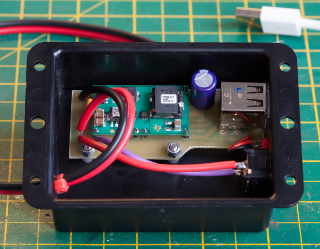
The completed charger is fitted into a plastic box with a power switch.


Ed Brookshire
Are kits, parts, or completed boards available?
Brian
Ed, I am sorry but I don't have any kits or completed boards for this project.