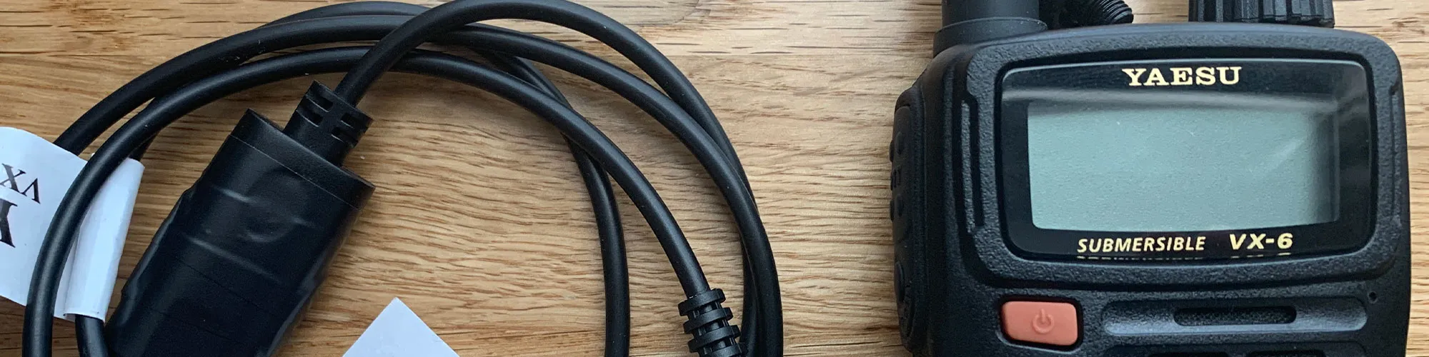
Last week I purchased a Yaesu VX-6 which is an ultra-rugged 144-430 MHz FM Hand-Held with wide receiver coverage of 504kHz to 998.99MHz.
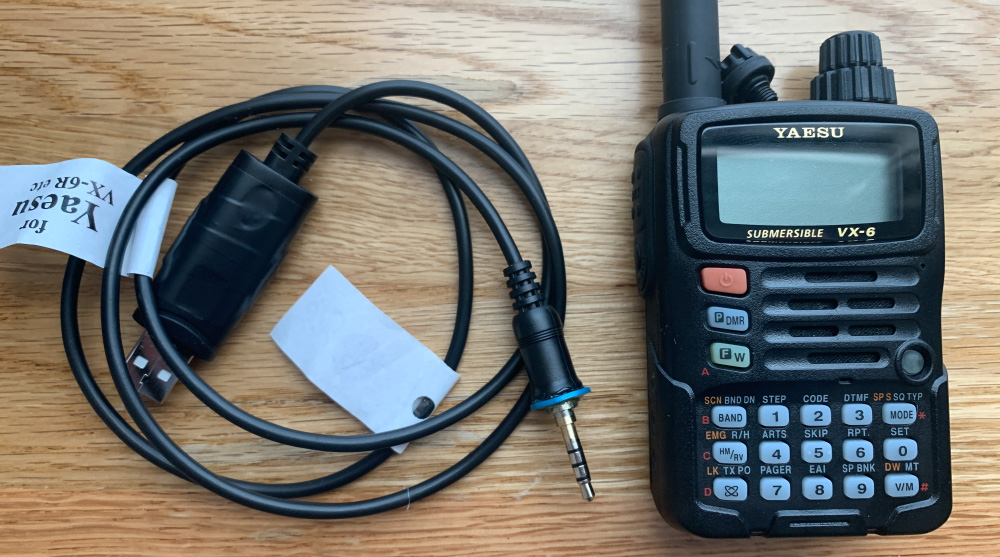
As programming the radios via the keypad is very time-consuming, I purchased a USB data cable from a UK seller on eBay and it arrived a few days later.
When connecting the cable to the radio and computer it would show as an FTDI USB-Serial interface, but the radio and software refused to communicate.
The Yaesu VX-6 uses a 4-way 3.5mm plug which screws into a recessed socket on the top of the radio. I was not sure if the connection to the radio was the problem so we removed the threaded portion of the plug using the lathe so we could try inserting the connector at different depths this did not resolve the issue so the problem appeared to be in the USB end with the FTDI chip and circuit.
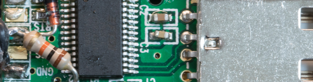
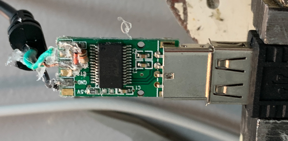
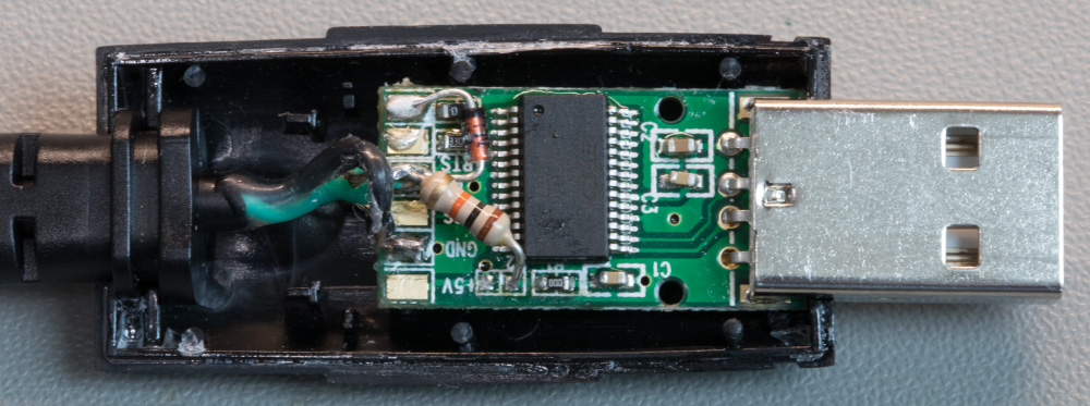
The USB connector is fitted to a small PCB in a plastic enclosure which easily came apart with a small amount of pressure on each side and is made of two plastic sides which had a small amount of glue holding them together.
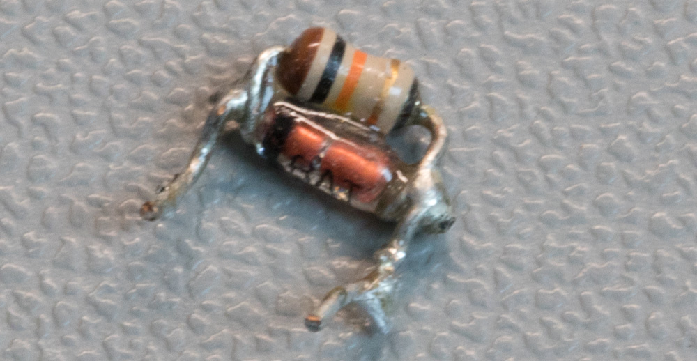
Removing the cover reveals the PCB with an FT232R USB UART IC, surface mount components with a 1N4148 diode and a 10K resistor across the TX and RX pins. The PCB was held in place using hot melt glue which was easily removed.
Data Format and Speeds
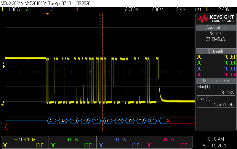
Connecting our Mixed Signal Oscilloscope to the cables going to the radio and setting it to Serial Data mode showed that the USB circuit was sending serial data at 19200 baud and at 5V levels.
The USB connector disconnected showing that the radio was sending a 3 Volt signal to the board.
The FT232R has a pin called VCCIO (pin 4) and this sets the data voltage level it can be powered by the 5V VCC to set 5V TX and RX levels or can be connected to pin 17 which is 3V3OUT to set the TX and RX levels to 3.3 volts.
Incorrect voltage levels
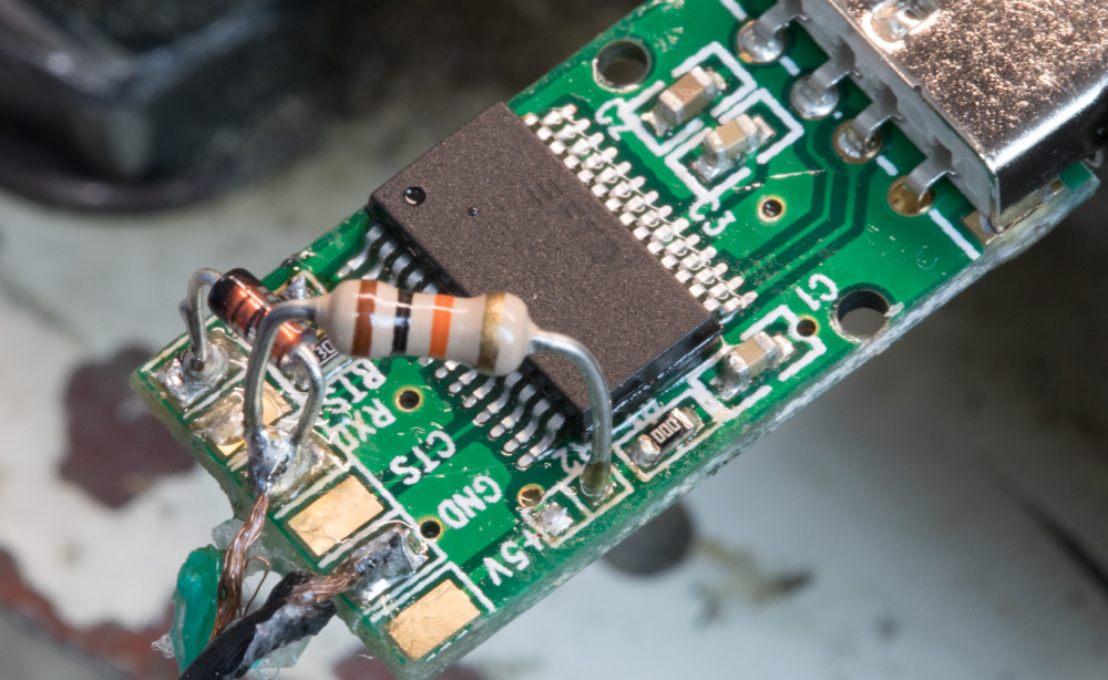
The circuit had the TX and RX in the 5V mode, and the PCB had a zero-ohm resistor for selecting the 5-volt or 3.3-volt levels. We changed the zero-ohm resistor to the 3.3-volt pads and using Putty on the computer showed that the computer was now able to read the initialise data from the radio but sending data from the computer was still not working so we couldn’t download or upload data to the computer.
The radio uses the same pin on the connector for sending and receiving data the TX pin on the FT232R had a 1N4148 diode with a 10K resistor in parallel between the TX and RX pins. This was supposed to allow the TX pin to pull low for sending data but was not functioning correctly.
I found several different circuit schematics for Yaesu cables and one on iz3zvo.altervista.org showed the 1N4148 diode connected between the DATA input from the radio and the TX pin but the 10K resistor was connected between DATA and the 3.3-volt pin. This acts as a pull-up for the TX and RX lines.
The new circuit schematic below shows the changes made.
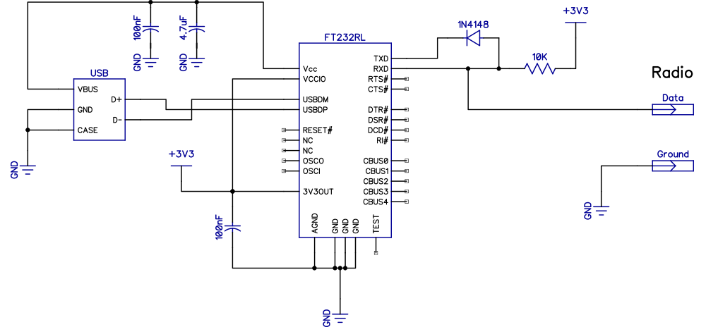
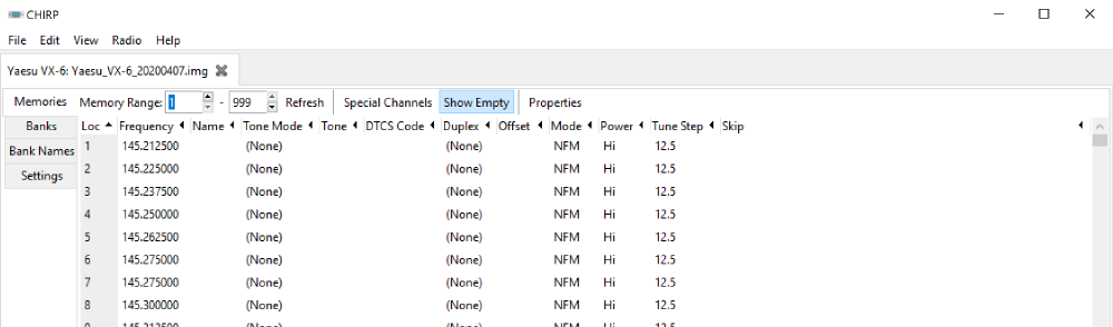
After changing the circuit to change the resistor to go to the 3.3-volt pin and the radio data line, we connected it to the computer and using Chirp or VX-6 Commander we were able to download the radios data and send updates back to the radio.


Gregg Lebovitz
This was a very useful article. I have an old prolific usb cable that use to work, but is no longer supported by windows. My guess is that it is using a fake chip and prolific figured out how to detect them. I am switching to a Silicon Labs CP21XX device and will need to add the diode and pull up resistor. Thanks.
Graham
Many thanks for this article. Like Gregg, I had a cable containing a Prolific PL2303TA clone that stopped working with Windows recently. I was about to make your modifications to a standard USB to serial lead, but noticed that the PL2303TA and FT232RL are pin-compatible, so it was 'simply' a matter of cracking open the plug and replacing the chip with an FT232RL. This may be a useful trick for resurrecting future driverless hardware!