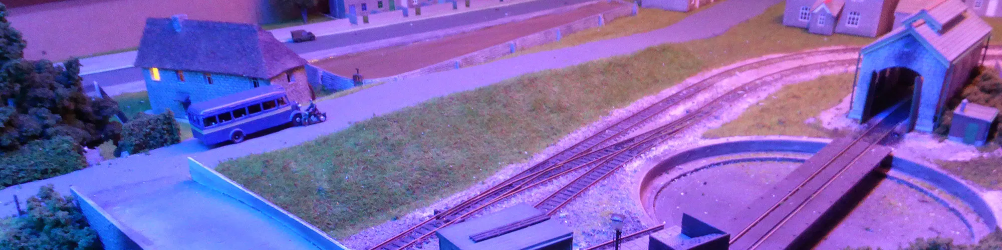
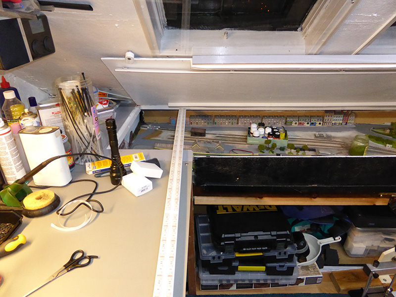
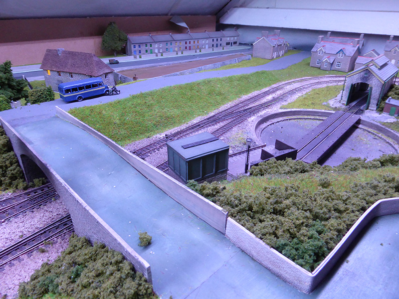
Alongside our electronic projects, another long-term hobby has been model making and more specifically model railways. We have had a model railway in our loft workshop for many years and it has always been a way of mixing the model-making and electronics hobbies. A long-term goal has been to make the railway computer controlled using a Raspberry Pi. The locomotives already run using digital command control with an off-the-shelf controller and once time permits this will be replaced with a custom-designed DCC command station that interfaces with a Raspberry Pi allowing full control over the railway using a tablet PC.
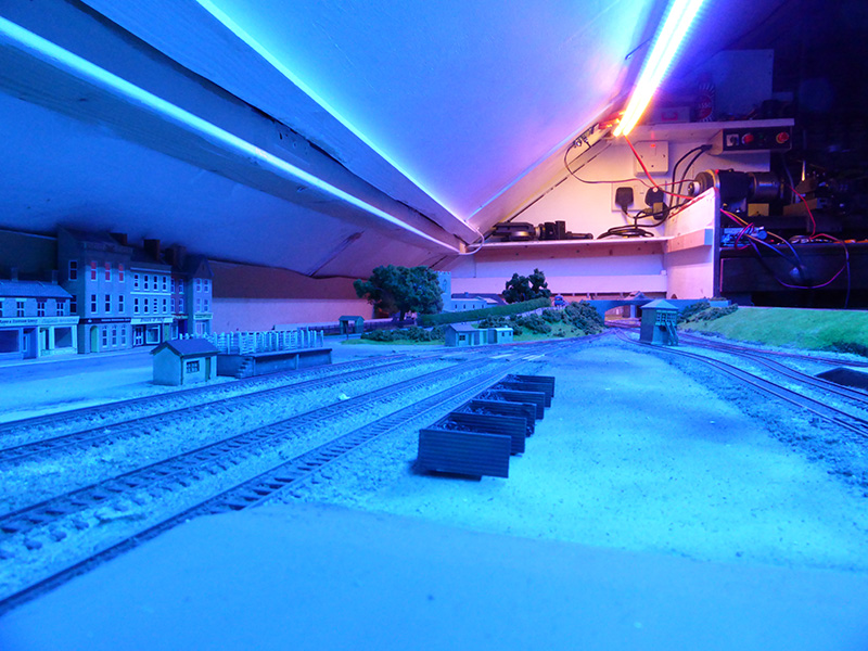
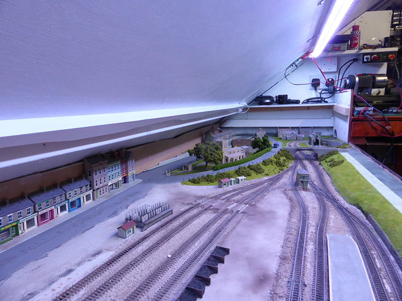
One feature you rarely find on other model railways is a way to control the lighting environment. Fluorescent tubes strung along above the railway are the normal method of lighting and while these give plenty of light it is difficult to make realistic lighting effects like nighttime or sunsets. With this in mind, we decided to try and design a lighting controller that would allow more accurate control over the environment. RGB LEDs would be used for generating the different lighting colours and a control system was needed that would allow manual control of several LED segments as well as remote control from a future computer interface.
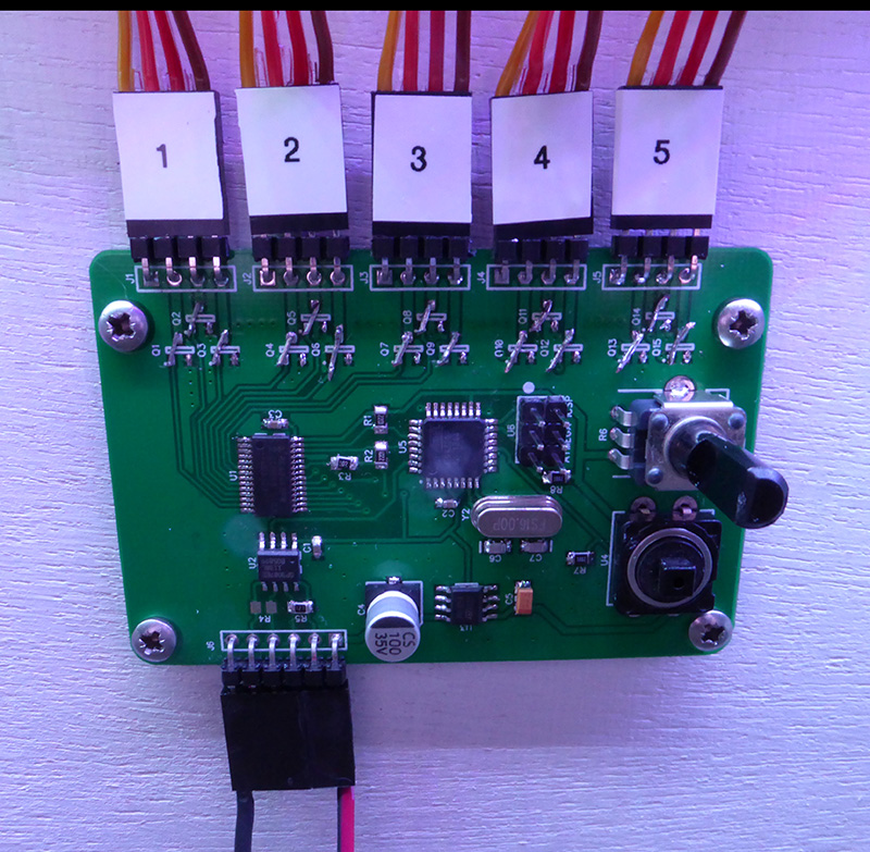
After looking at the various ways we could control the LEDs we settled on the PCA9685 16-channel 12-bit PWM controller from NXT. This controller can be interfaced with a microcontroller over an I2C interface and can directly drive 16 MOSFET drivers without the need for pull-up or pull-down resistors. As RGB LEDs use three channels for the individual colours it would be possible to drive up to 5 separate LED segments on a single PCA9685 controller. Some LED strips were purchased from eBay and work began on designing an interface for the PCA9685 controller. The LED strips run from a 12V supply so a 7805 linear regulator was used to drop the 12V down to 5V for running the control circuit.
An ATmega328P microcontroller was chosen for driving the LED controller. This is the same microcontroller used on the Arduino UNO so the Arduino compiler could be used to design the software for the controller and then programmed onto the board using an AVR Dragon programmer. A Maxim MAX3087 RS485 interface IC was chosen for talking to a future computer controller. By using RS485 a single data bus can be used to communicate with all of the microcontrollers on the model railway allowing for simpler expansion in the future. The MAX3087 is a full-duplex controller which means it needs four data wires to communicate but it is easier to design the software on the host and slaves as you do not need to switch the data direction when each device on the bus communicates with the host as you would on a half-duplex network.
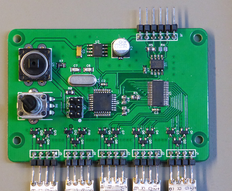
For the manual control part of the design, a button and potentiometer were added to the circuit. The button is used for selecting the mode and the potentiometer sets the time of day or brightness.
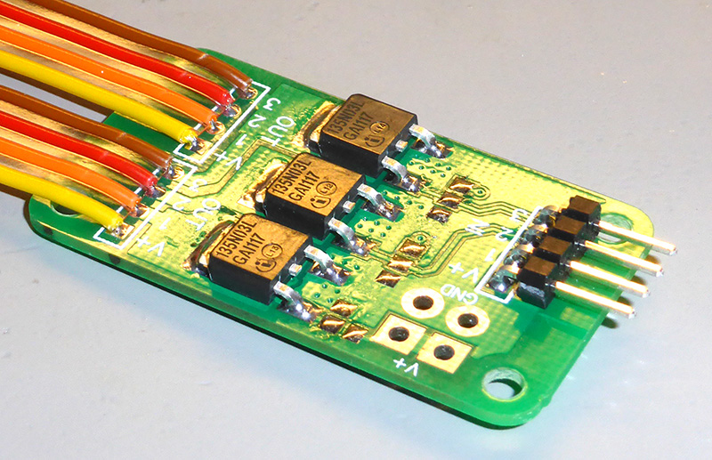
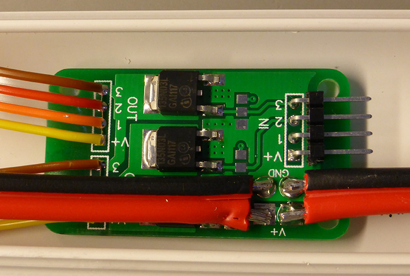
A circuit was designed with all of the ICs and MOSFET drivers on a single board. When we designed the circuit the LED strips had not arrived yet from China so a guess was made on how much current they would consume and some small MOSFETs were selected to fit on the board. After the LEDs arrived we found that the number needed to light the railway would consume around 30W of power which was more than the original MOSFETs could handle so a new set of driver boards with higher-rated MOSFETs was designed which would be soldered onto the ends of the LED strips and connect to the control board via ribbon cables. The original MOSFETs were unsoldered and some wire was used to bridge the pads between the control IC and the output pins.
The software was designed to make controlling the LEDs as simple as possible. The program starts by initialising the PWM controller and serial interface and then loads up the control mode from an EEPROM address which is saved on each button press. Saving the current mode in EEPROM allows the controller to resume its previous mode when it is turned on. There are three modes which can be selected using the push button on the board.
Brightness mode sets all of the led channels to white and allows you to control the overall brightness with the potentiometer.
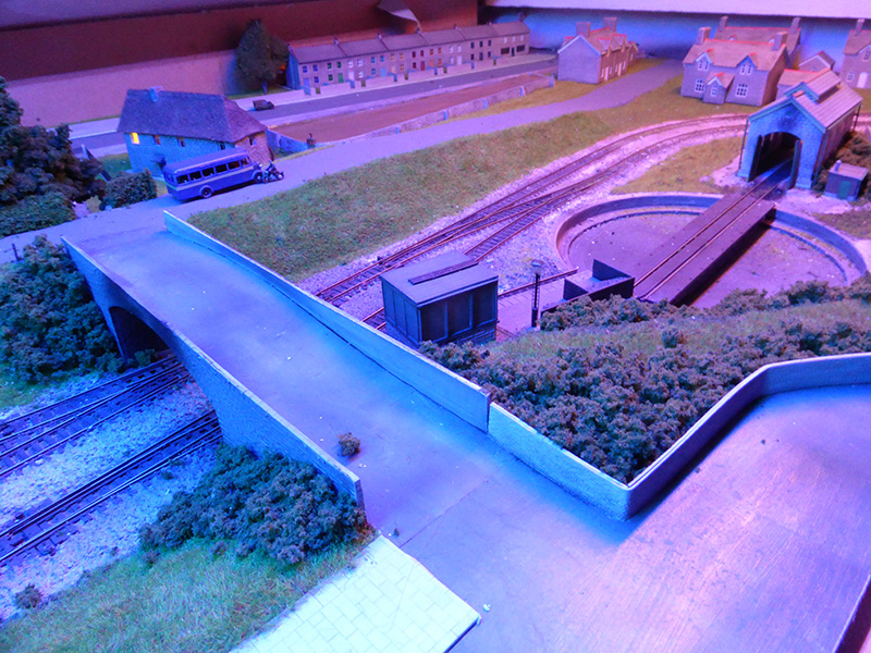
Time of day mode has 24 pre-set colour schemes that simulate different times of the day so you go from a dark blue at night time to sunrise and then daylight getting brighter until mid-day and dimming slowly before sunset and night time again. The time of day is adjusted with the same potentiometer as the brightness mode.
The third mode switches the LEDs off and sets the output-enable pin high on the PWM controller disabling all of the outputs.
To make it easier to tell which mode you are in the controller flashes one of the LED channels with a different colour for each mode, red shows that the controller is off, green shows it is in time of day mode and blue shows it is in brightness mode.
As well as the local control system a protocol was designed to allow remote control over the RS485 bus. Each data packet begins with an address byte followed by the number of bytes that will be sent in the packet. The address byte allows you to have up to 256 devices on the same bus with the controller only responding to commands that contain an address byte of 0x02. The packet length byte was used to allow command packets of different lengths and for the controller to know how many packets to expect. A final verification byte of 0xFF is sent at the end of the packet so the controller can check if a complete packet was sent. The controller will only respond to a packet if the address byte is correct, the packet length is correct and the packet ends with the verification byte.
At the moment the controller responds to four different remote commands. The first two commands are used to switch the controller on and off while the third command allows you to set the RGB value on a single LED channel and the fourth command sets the time of day. As the PWM controller uses 12 bits for each colour 6 bytes were needed for specifying the values for all three colours giving a possible 68 billion colour combinations.
The circuit diagram along with the software and serial protocols can be found at github.com/briandorey/Sky-LED-Controller
The video below shows the circuit being used in manual mode to change the colours of the LED arrays.


Michael
Amazing. This is a great project to make a layout next level.
Michael
Amazing. This is a great project to make a layout next level.
Christian Grenier
Hi,
Can we use another programmer other than the AVR Dragon to program the ATmega328P from the Arduino IDE?
Thanks
Chris
Christian Grenier
Hi,
Here are my tests. To program my Atmega328P I used the USBasp programmer and the AVRDUDESS software. It works great!
Amazon USBasp:
https://www.amazon.ca/Robojax-Convert-Standard-Adaptor-Programmer/dp/B07DL61WZR/
AVRDUDESS:
https://blog.zakkemble.net/avrdudess-a-gui-for-avrdude/
Thanks,
Chris