
For a few years now we have been using a GW Instek GPC-1850D power supply in our workshop and while it has served us well over that time there has always been one issue that has annoyed us, the loud cooling fan in the back which drowns out everything else in the room. For everyday projects, this fan noise is only an irritation but for anything which is noise sensitive like audio projects, it can become more of a problem.
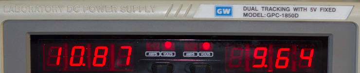
We didn’t want to replace the power supply as it still works perfectly well so the other option was to try and reduce the noise of the fan. Most of the projects we build only consume a few milliamps of current so the 5A supply is rarely used near its capacity. What we needed was a way of regulating the fan speed so it runs slowly during normal use but will speed up when the power supply gets hot.
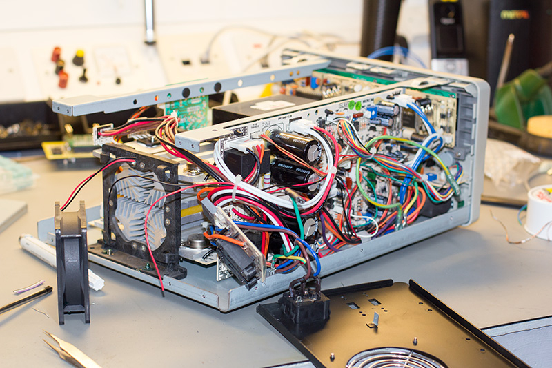
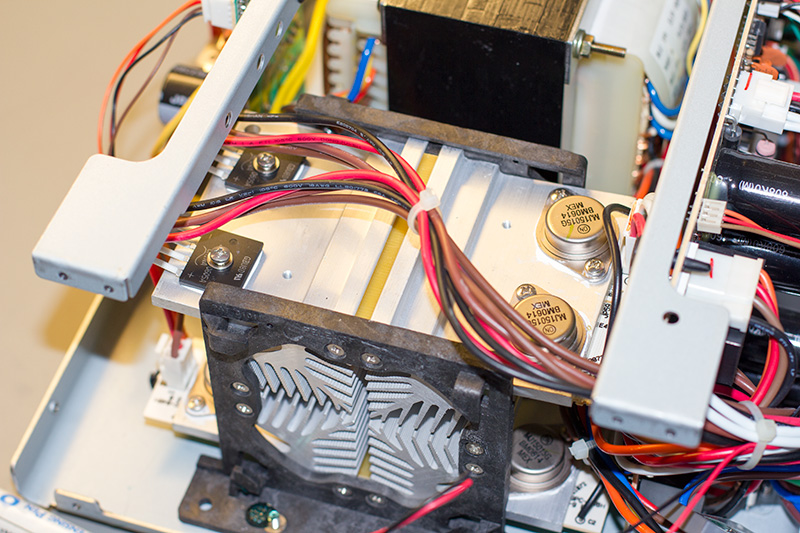
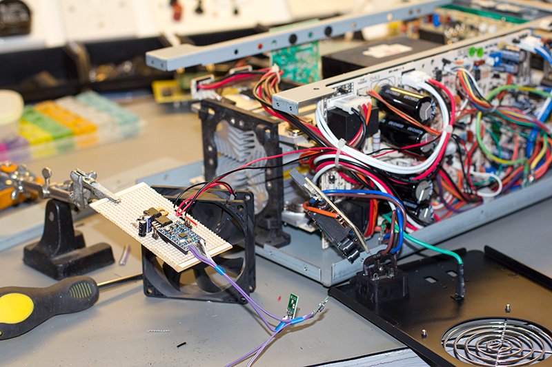
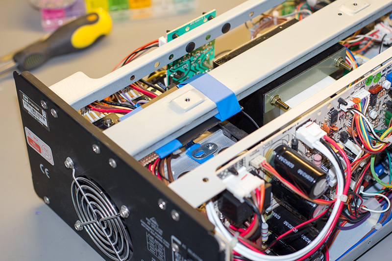
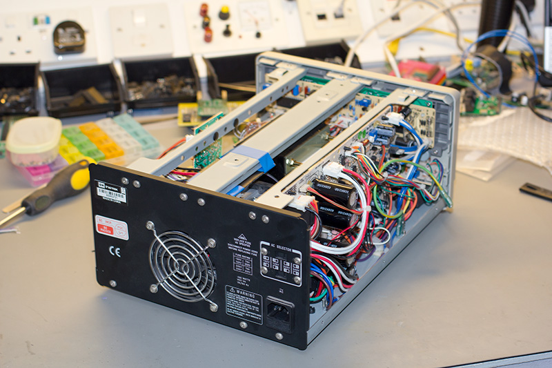
The first job was to take the cover off of the power supply and see what was inside. The GW Instek supplies are fairly well built and easy to disassemble so a few bolts later and the cover came off revealing a large transformer in the middle with a circuit board down one side and a heat sink at the back in front of the fan. After taking the back cover off we found that the heat sink is actually four separate heat sinks electrically isolated from each other using fibreglass spacers. It looks like one of the heat sinks is used for cooling the bridge rectifiers while the other three are used for the power transistors on the three output channels. As the four heat sinks are electrically and thermally isolated and they would change temperature depending on which channel is being used each one would need its own temperature sensor.
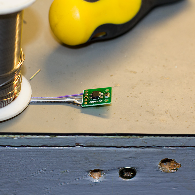
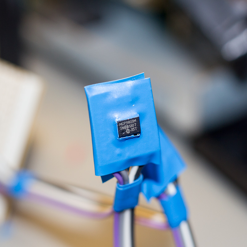
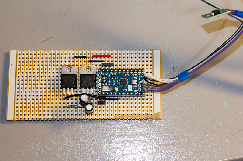
We had several Microchip MCP9803 temperature sensors left over from a previous project. The MCP9803 uses an i2c interface to communicate with a host and has address selection pins so four of them could be connected together on the same i2c bus. As this was to be a quick build and I didn’t want to spend hours building a PCB we decided to use an Arduino Mini for communicating with the temperature sensors and build the project on a piece of stripboard.
The fan on the power supply runs at 24V and it doesn’t look like there is any speed regulation built into the supply so we decided to use this 24V supply to power the Arduino and the fan. As Arduino Minis run at 5V a 7805 regulator was used to drop the voltage. The Arduino only uses a few milliamps of current so a heat sink wasn’t needed on the regulator.
The Arduino reads the temperature from each sensor and gets the highest temperature from the four heat sinks. The fan speed is controlled using a PWM output from the Arduino which drives a MOSFET connected to the fan. As the power supply needs some airflow to cool the transformer and other internal components it would need to keep the fan running slowly at all times.
After playing around with different fan speeds we found that a speed of 20% gave some airflow with very little noise so this was used as a base speed for when the power supply is cold. Once the heat sinks reach 30°C the speed is increased to 40% and then gradually increased at 5°C intervals until it is running at full speed at 65°C. We wrote the code for the Arduino and then tested the fan output by holding a soldering iron over one of the sensors to warm it up.
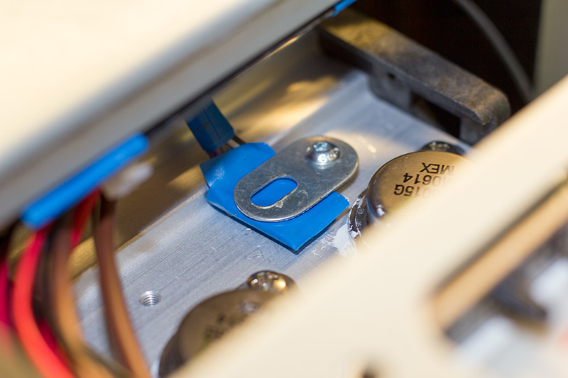
Once we were happy that the circuit was working properly we transferred it to a piece of stripboard, added some insulation to the back and insulated the temperature sensors and went about installing it into the power supply. Each heat sink had a pair of spare M3 threaded holes in them so a clamping system was devised using some mechano and washers. Some thermal paste was used to make good contact between the sensors and the heat sinks.
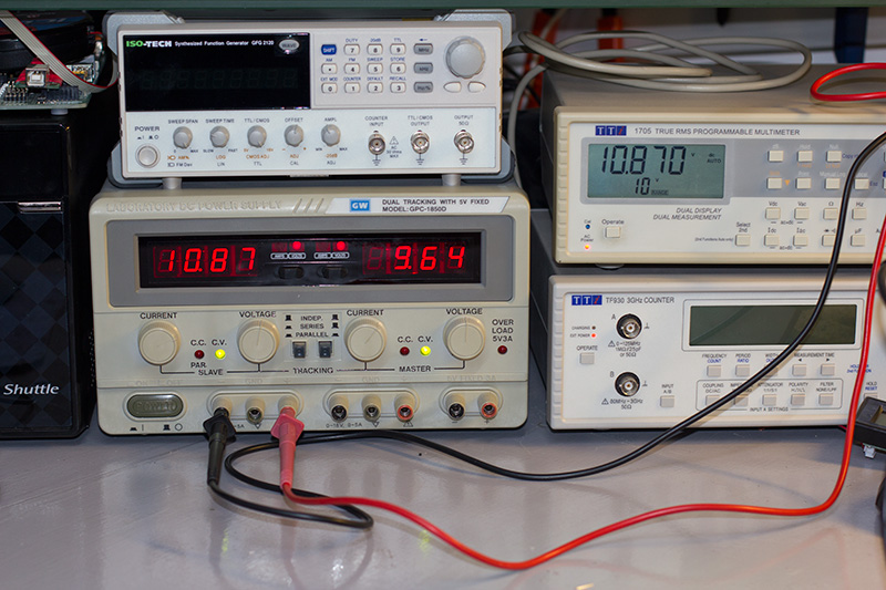
The control board was taped underneath a bar which runs across the top of the chassis and the power supply was reassembled. After some initial testing, it all appears to be working well and the new addition hasn’t affected the output voltages in any way.
The workshop is now a lot quieter when we are working on our projects.
The circuit schematic and code can be downloaded from https://github.com/briandorey/PSU-Temperature-Monitor


Comments