In 2015 we tried to add an optical interface to our Mastervolt Soladin 600 solar PV inverter to access the data from the inverter to use with our smart home logging software but due to excessive RF noise radiated from the inverter, this approach failed.
Now that Wi-Fi modules are much more affordable, we decided to try to monitor the data via Wi-Fi to our MQTT server. We found a library which had been changed to work with the ESP8266 modules, you can download the updated library from github.com/vChrisR/SolaDin
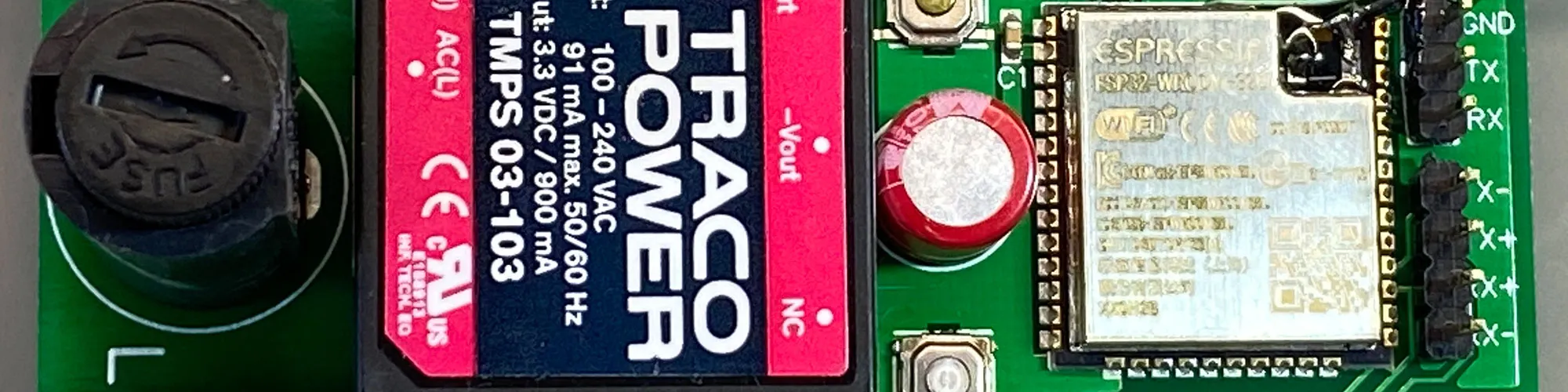
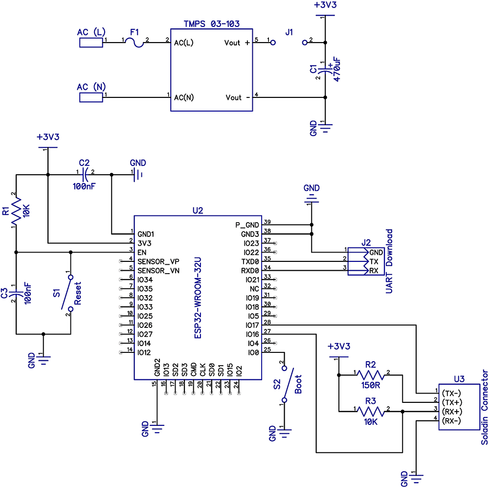
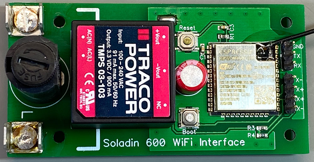
Andrew designed a small PCB based around the Espressif ESP32-WROOM-32UE(M113EH2800UH3Q0) which is an ESP32 ECO V3, with 16 MB SPI flash and an IPEX antenna connector allowing the use of an external antenna. A mains power supply and associated components were added to the circuit to make it completely self-contained and capable of running from the 240V available inside the PV inverter.
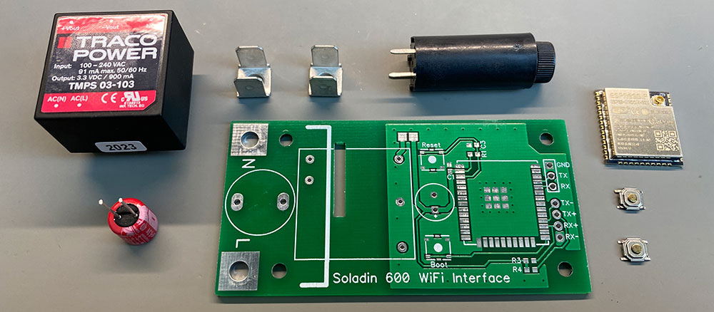
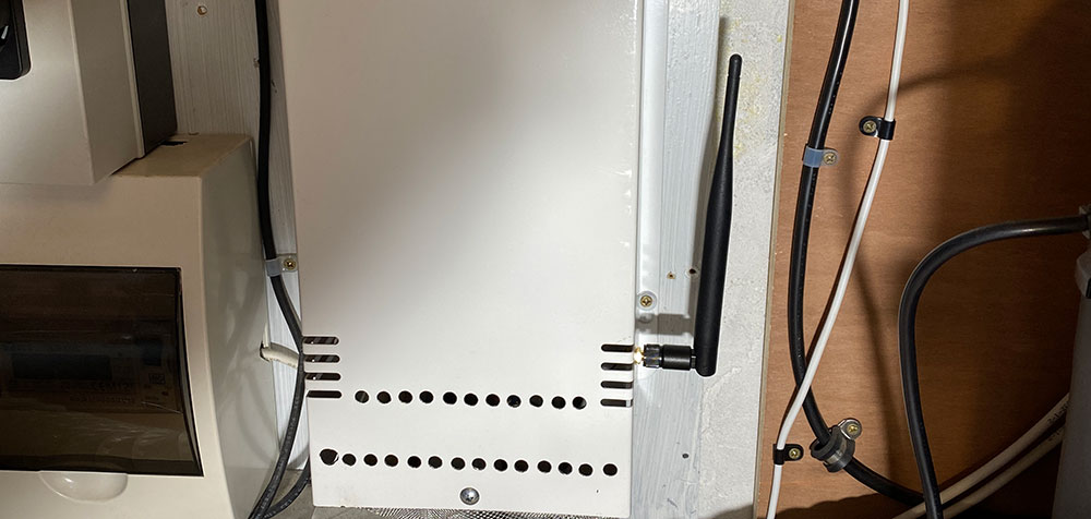
A Wi-Fi antenna, salvaged from an old ADSL router, was fitted with a short pigtail lead and a U.FL connector which connects to the ESP32 module.
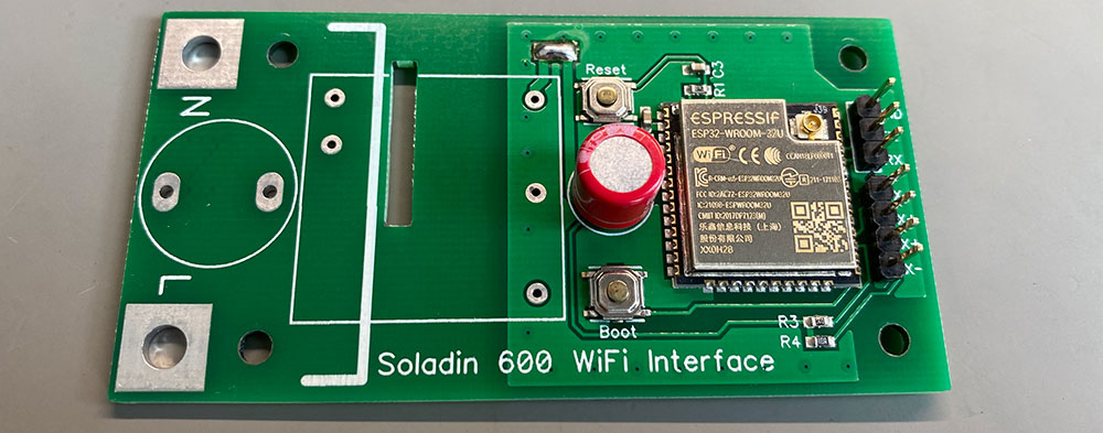
Whilst assembling the board we had an issue with the antenna connector which broke away from the module, so we had to solder the small coax direct to the PCB traces on the module and hold in place using epoxy resin.
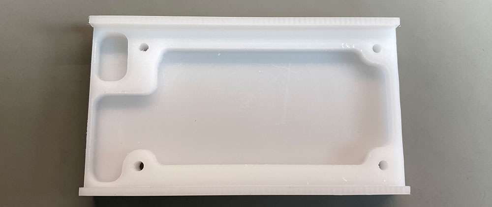
To keep the PCB away from the metal inverter enclosure we machined a mounting plate from some acetal plastic.
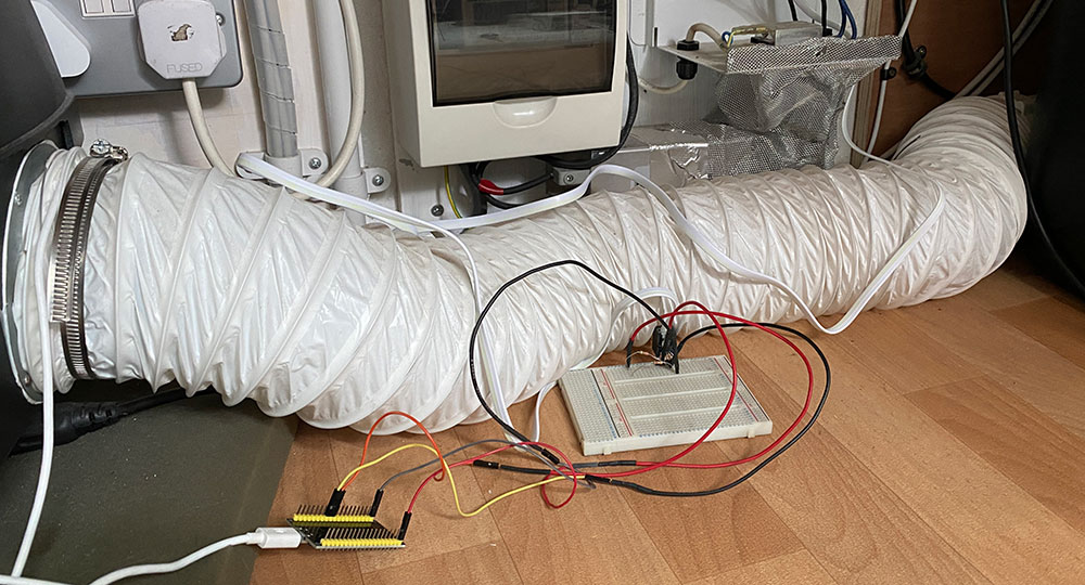
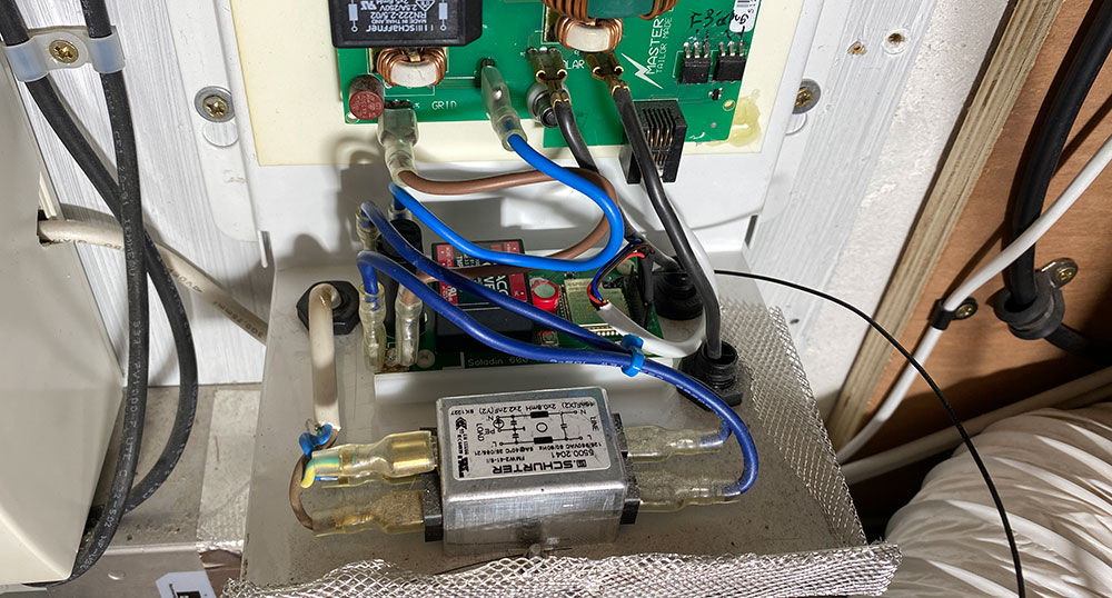
The PCB was fitted into the inverter's metal case with the plastic mounting plate and the antenna was fitted through the side of the case.
The connection to the inverter PCB is via a short cable with an RJ12 connector which uses four of the six available pins.
The inverter outputs data on the following pins:
3 – TX +
2 – TX –
4 – RX +
5 – RX –
Parts List:
| RefDes | Name | Pattern | Quantity | Manufacturer |
|---|---|---|---|---|
| C1 | 870025174006 - 470 µF, 6.3 V Polymer Aluminium Electrolytic Capacitor | 3.5mm Pin Spacing / 8.5mm Diameter/ 12mm Height | 1 | WURTH ELEKTRONIK |
| C2, C3 | 100nF SMD Ceramic Capacitor | 603 | 2 | |
| F1 | BK1-H15-V-1 5 x 20mm Fuseholder | 1 | BUSSMANN BY EATON | |
| J1 | Solder Bridge | 1 | ||
| J3 | 3 Pin 2.54mm Header | 1 | ||
| R1, R3 | 10K SMD Resistor | 603 | 2 | |
| R4 | 150R SMD Resistor | 603 | 1 | |
| S1, S2 | EVQPT9A15 Tactile Switch | 2 | PANASONIC | |
| TP1, TP3 | 42802-1 PCB Terminal | 2 | AMP - TE CONNECTIVITY | |
| U1 | ESP32-WROOM-32U WiFi Module | 1 | ||
| U2 | TMPS 03-103 AC/DC PCB Mount Power Supply | 1 | TRACOPOWER | |
| U3 | 4 Pin 2.54mm Header | 1 |
The Firmware
The firmware to run on the ESP32 module was written using VS Code with the Platform IO plugin installed.
The structure of the program is simple. On start-up, the program connects to the Wi-Fi network and MQTT broker and polls the inverter for the current data values. Once the serial data is obtained it is posted to the MQTT broker and the ESP32 module is put into a deep sleep mode which disables everything except the ULP coprocessor and the RTC. The RTC timer is used to wake the module after 10 seconds where it repeats the previous steps.
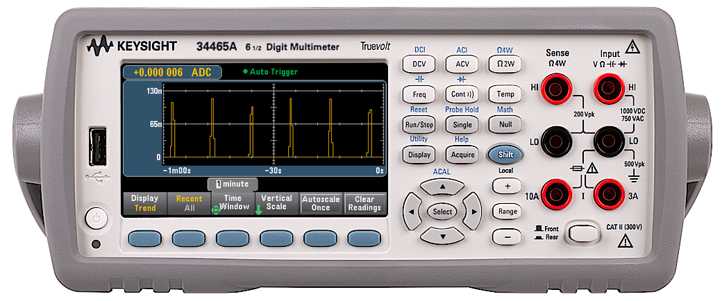
The ESP32 module uses around 150mA when connected to the Wi-Fi network but in deep sleep mode, it uses approximately 10µA so by keeping the module asleep for most of the time and only waking to retrieve the data from the inverter the overall power consumption is greatly reduced.
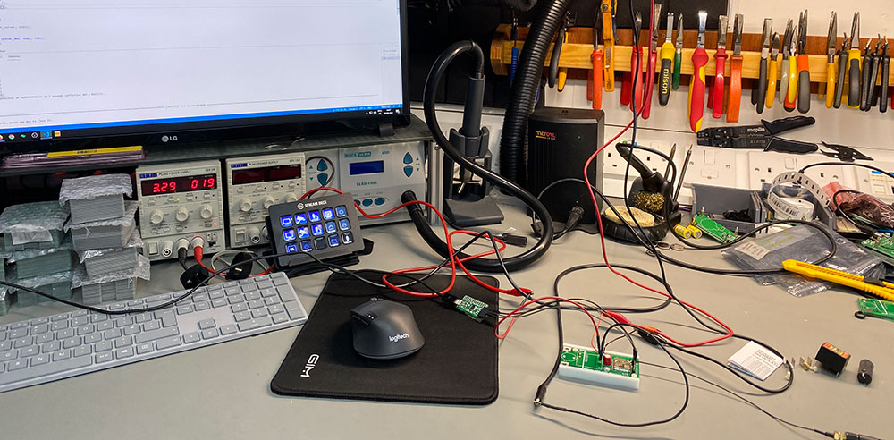
During development, we connected the circuit to our bench multimeter to monitor the current consumption. Two pads were added to the PCB to allow us to connect the multimeter in series between the switch-mode PSU and the ESP32 module. Once we finished development a solder bridge was used to join the two pads.
The screenshot below shows the multimeter display while the circuit is running.
Home Assistant
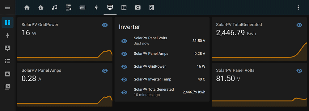
With the new solar PV data being sent to our MQTT server we can add the new devices to the sensors list on Home Assistant and add a new page to show the data.
The code to add the MQTT sensors is below:
- platform: mqtt
  state_topic: "/home/solarpv/pvvolt"
  name: "SolarPV Panel Volts"
  unit_of_measurement: V
- platform: mqtt
  state_topic: "/home/solarpv/pvamp"
  name: "SolarPV Panel Amps"
  unit_of_measurement: A

- platform: mqtt
  state_topic: "/home/solarpv/gridpower"
  name: "SolarPV GridPower"
  unit_of_measurement: W
- platform: mqtt
  state_topic: "/home/solarpv/totalpower"
  name: "SolarPV TotalGenerated"
  unit_of_measurement: Kwh
- platform: mqtt
  state_topic: "/home/solarpv/devicetemp"
  name: "SolarPV Inverter Temp"
  unit_of_measurement: C
To be able to use the new data with the Energy tab, a new template sensor needs to be added with the following code:
- platform: template
  sensors:
    energy_solar_pv_in:
      value_template: "{{ (states('sensor.solarpv_totalgenerated') | float)}}"
      unit_of_measurement: "kWh"
      friendly_name: "Incoming SolarPV"
Downloads
The files and code for this project can be downloaded from GitHub.
Update 21st August 2021
Less than 24 hours after being installed the power supply module failed and is no longer supplying the 3.3 volts needed.
With the board on the bench, the TRACO POWER TMPS 03-103 AC/DC PCB Mount Power Supply is making arching noises and is very hot despite the current draw of the Wi-Fi module being less than a quarter of its rated current of 900mA.
With the mains supply removed, we powered the board using our bench supply and it is working correctly.
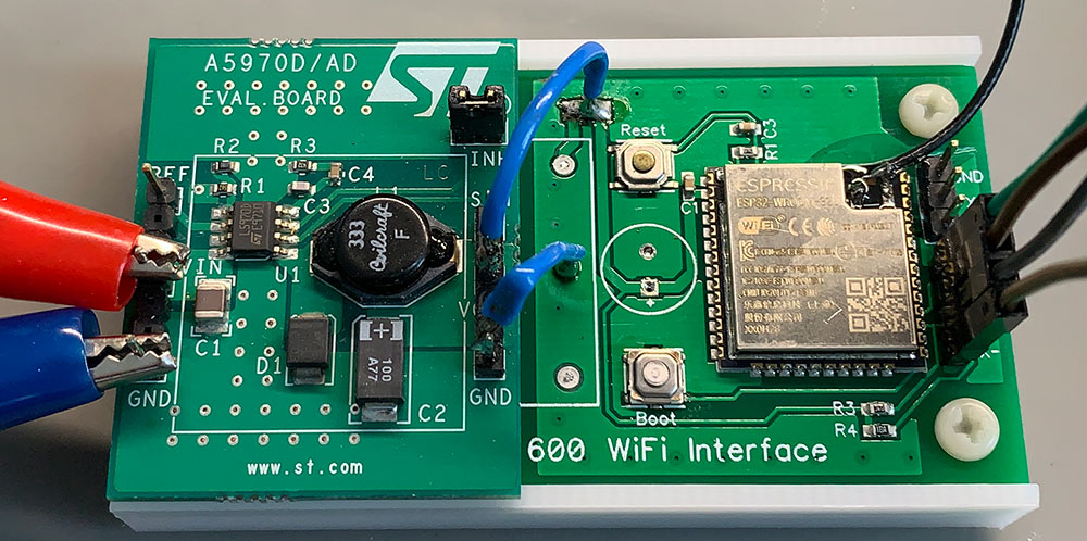
We have several drawers full of different DC-DC regulators and modules and we have an A5970AD a step-down monolithic power switching regulator on an evaluation board which outputs 3.3 volts and can accept an input voltage of up to 40 volts.
We have a 12-volt power supply in the network cupboard below the loft which runs cooling fans and other low-voltage equipment, so we added a new low-voltage power cable to supply 12 volts DC to the loft and this was connected to the evaluation board and then this was fitted in place of the old mains power supply.


solipso
Why have you removed that fancy electrolytic capacitor? The boared is nowhere near as nice as it was with that nice red device on it.
Brian
We didn't need the electrolytic capacitor with the DC-DC converter power supply.
loet van den bosch
Can you also make more MasterVolt devices in the system?
Alan
Hi there.
Could you sell/supply one of these prebuilt or the Pcb ?
Any news on the psu issue ? Do you think it was just a weak psu or something else ?
Thanks for a great project.
Brian
Hi, I am sorry but we dont have any of the pcbs now or the modules. We replaced the inverter a few years ago.