Our Home Assistant setup now has over 340 sensor devices and entities. While the main user interface is very useful for viewing all the data, we would like to have a smaller display in the house to show just two or three sensor values and have this accessible away from desktop computers and tablets.
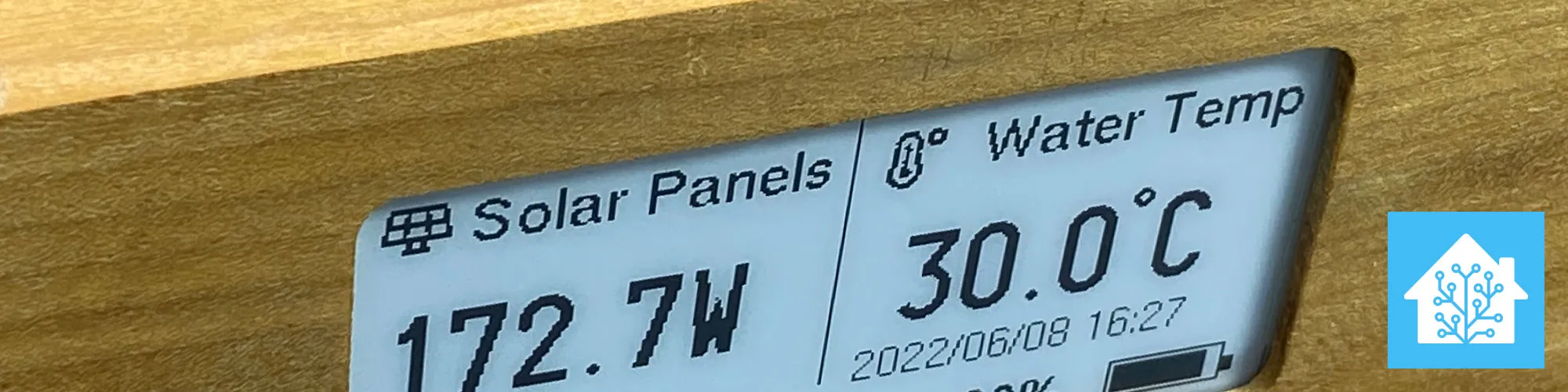
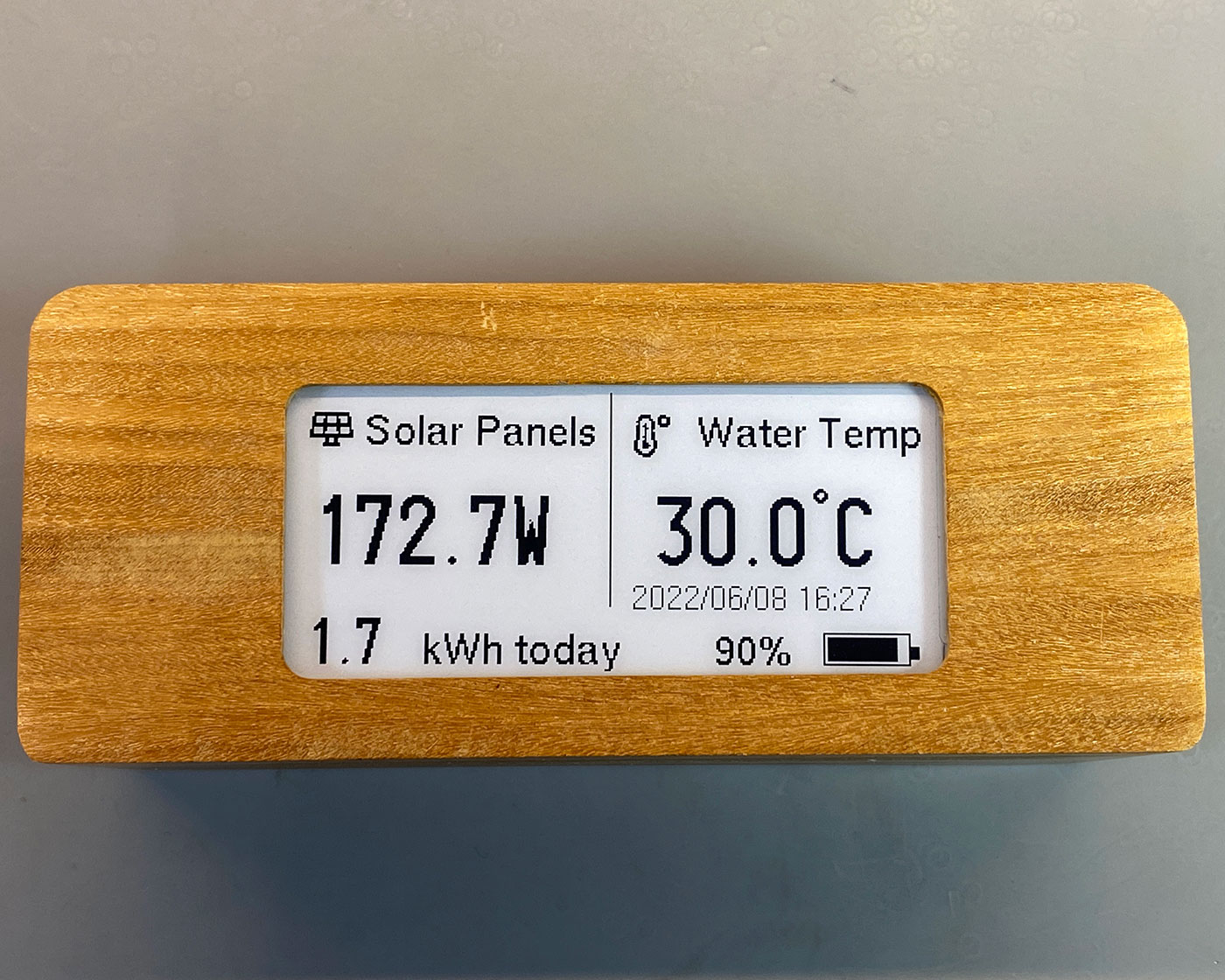
We wanted to show the Solar PV input in watts, the daily generation total and the temperature of the hot water cylinder. The display will be going into the kitchen so we can easily see if there is hot water available for cleaning or if we need to boil a kettle.
The remote display needed to have the following features:
- Compact Size
- Low Power Consumption
- Battery Powered
- WiFi
- Use REST or MQTT for data
- Black and White display
- Refreshed every few minutes
An ePaper or eInk display module meets all these requirements, and the modules are available with ESP32 WiFi microcontrollers and battery management built into the single circuit board.
After looking at various ePaper display modules, we ordered a DollaTek T5 V1.3 ESP32 2.9 inch EPaper Plus electronic ink screen development board from Amazon https://amzn.to/3w051RY which is a 2.9" e-paper module 296 x 128 pixels and runs on an ESP32 MCU.
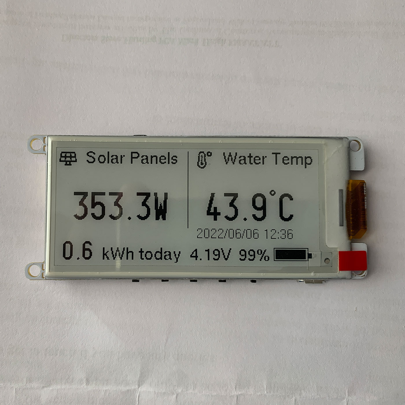
The DollaTek T5 V1.3 is a rebranded Xinyuan LilyGO T5 2.9", version 2.2 display and this project is based on code and setup instructions from https://github.com/Xinyuan-LilyGO/LilyGo-T5-Epaper-Series and battery display from https://github.com/CybDis/Lilygo-T5-47-HomeAssistant-Dashboard/
The data for the display is fetched from Home Assistant https://www.home-assistant.io/ via the REST API https://developers.home-assistant.io/docs/api/rest/ and displays sensor data on the e-paper display.
Getting Started
The code for this project is available to download from GitHub at https://github.com/briandorey/Home-Assistant-eink-remote-display.
- Install the following dependencies
- Copy all the folders in the lib directory to
"C:\User\\Documents\Arduino\libraries" - In Arduino IDE, select
ESP32 Dev Modulein the development board, and keep the other options as default - If you do not find the ESP32 series in the development board, then you should see the following installation method How to install ESP32 in ArduinoIDE
- In your Home Assistant install, select the profile page and generate a new
Long-Lived Access Tokens
Configuration
In epaperdisplay/epaperdisplay.ino update the following lines to your WiFi and network settings.
// Network Settings
const char* ssid = "YOURWIFISSID";
const char* password = "YOURWIFIPASSWORD";
/* Put StaticIP Address details */
IPAddress local_ip(192.168.1.1); // Set static IP
IPAddress gateway(192.168.1.1); // Set network Gateway IP
IPAddress subnet(255, 255, 255, 0); // Set static IP
IPAddress primaryDNS(8, 8, 8, 8);   //optional
IPAddress secondaryDNS(8, 8, 4, 4); //optional
Enter your Home Assistant IP address and access token.
// Home Assistant IP and token key
const char* ha_ip = "192.168.1.10";
uint16_t ha_port = 8123; // Could be 443 is using SSL
const char* ha_pwd = "YOURTOKEN";  //long-lived password. On HA, Profile > Long-Lived Access Tokens > Create Token
Set your sleep period in minutes between the display updates
// deep sleep configurations
long SleepDuration   = 1; // Sleep time in minutes
Overnight sleep mode (optional)
The DoNightSleep() function allows you to sleep the display for a selected number of hours, line 137 sets the number of minutes to sleep, and the code is set at 540, which is 9 hours.
SleepTimer = (540 * 60);
Lines 173 to 176 allow you to set the time that NightSleep is enabled, with the hour being obtained from a time sensor in Home Assistant called: sensor.date_time_iso
 if (timevar[11] == '2' && timevar[12] == '2') {
   TRACE("night sleep");
    //DoNightSleep();
        }
The sensors which are shown on display are set with the following:
float fltHotWater = ParseSensorJsonData( ha.sendGetHA("/api/states/sensor.hot_water_top"));
  //String val = ha.sendGetHA("/api/states/sensor.hot_water_top");
  TRACE("Hot Water Top: ");
  TRACE(fltHotWater);

  float fltSolarPVWatts = ParseSensorJsonData( ha.sendGetHA("/api/states/sensor.solarpv_total_meter_gridpower"));
  TRACE("Solar PV Watts: ");
  TRACE(fltSolarPVWatts);

  float fltSolarPVGenerated = ParseSensorJsonData( ha.sendGetHA("/api/states/sensor.solarpv_todaygenerated"));
  TRACE("Solar PV Generated: ");
  TRACE(fltSolarPVGenerated);


  ParseTimeJsonData( ha.sendGetHA("/api/states/sensor.date_time_iso"));
Battery Monitoring (optional)
If you are running the display from a battery, you can add a battery meter using the DrawBattery() function. This is using code modified from https://github.com/CybDis/Lilygo-T5-47-HomeAssistant-Dashboard/tree/master/src
Power Consumption
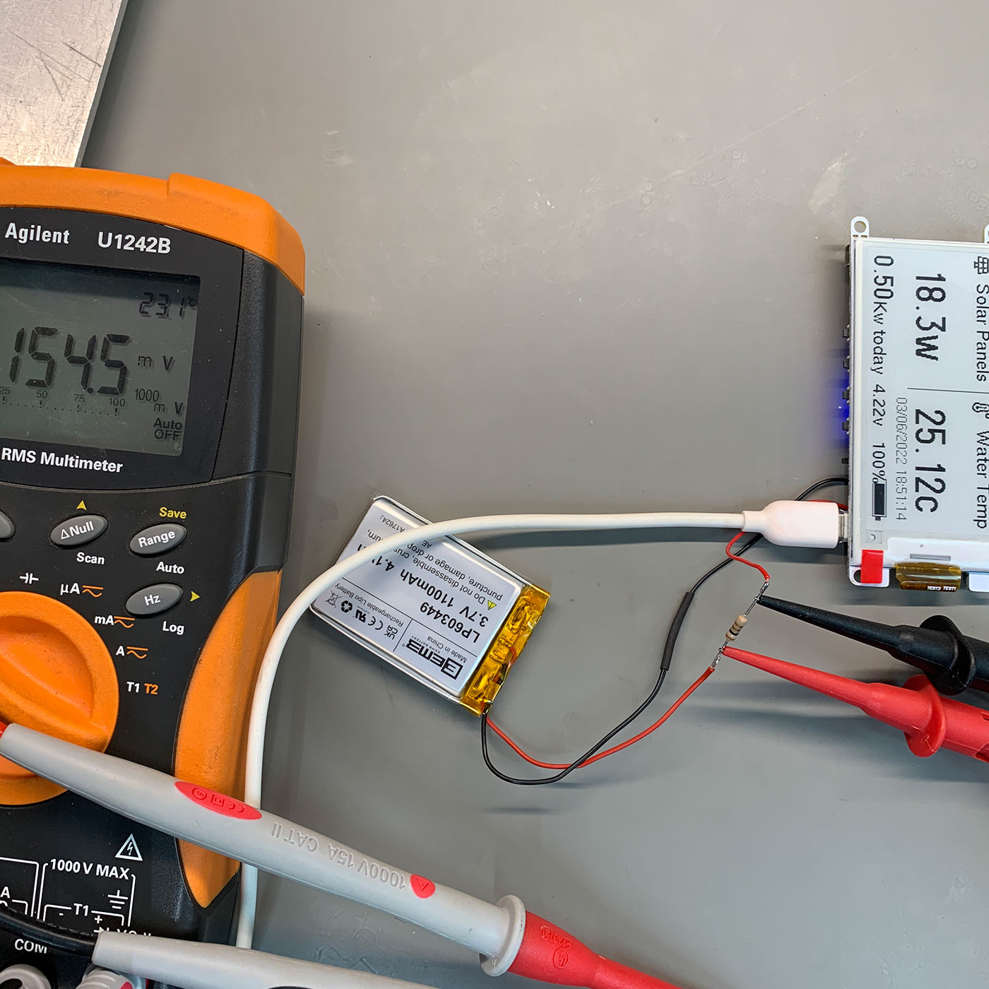
We measured the current consumption using a Keysight 34461A 6½ digit, Performance Truevolt DMM and our Keysight Oscilloscope measuring across a 1-ohm resistor and calculated the current from the resulting voltage.
The display was powered using an EEMB 3.7V 1100mAh 603449 Lipo Battery Rechargeable Lithium Polymer ion Battery Pack (https://amzn.to/480ZNTk)
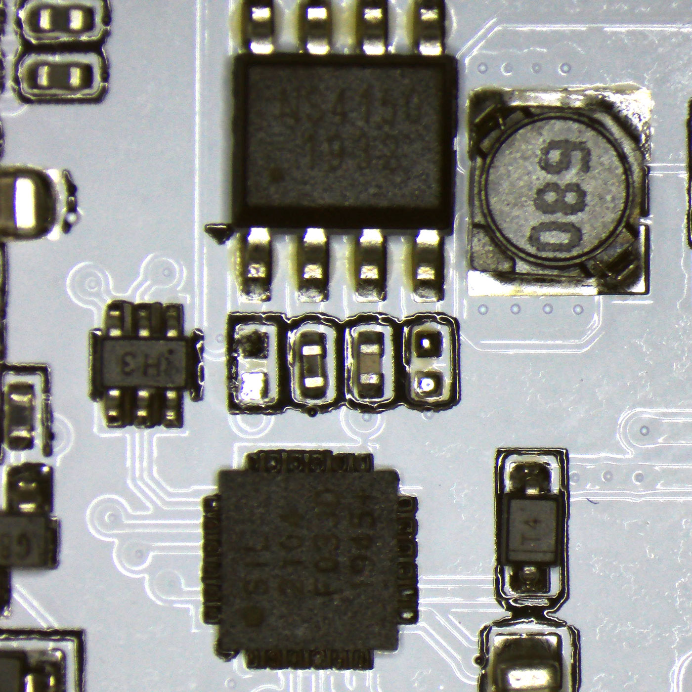
Removing R32, which enabled the pullup on the audio IC, reduced the hibernate power consumption by an additional 5mA.
The wake and update state uses approx. 153mA takes under 0.4 seconds to connect to WiFi and retrieve the data; the display takes 3.5 seconds to update then the board returns to hibernate mode.
| Mode | Current in mA |
|---|---|
| WiFi Connected Peak | 160 |
| Deep sleep | 46.5 |
| Green LED Removed | 45.8 |
| Update from REST API | 153 |
| Hibernation mode | 6.8 |
| R32 audio pullup removed | 1.8 |
Battery Pack Sizes
Using the EEMB 3.7V 1100mAh 603449 Lipo Battery, we found that the display would only run for 10 hours.
Based on the power consumption, this should have lasted much longer, but the battery must be at a lower capacity than advertised.
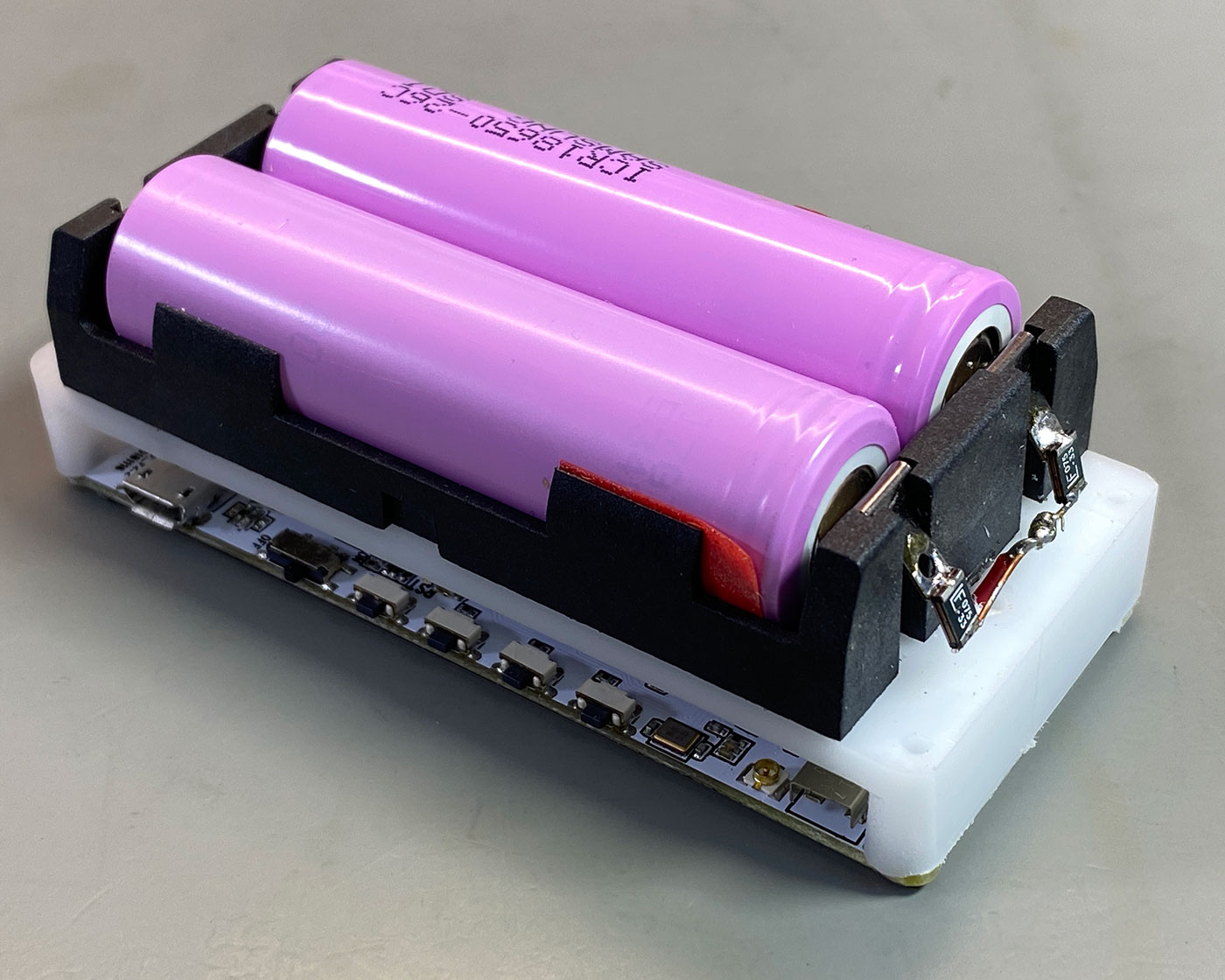
As this was not suitable for a standalone display, we decided to use a pair of 18650 2500mAh cells connected in parallel. This gives a much longer runtime and can easily be removed from the battery holder for charging.
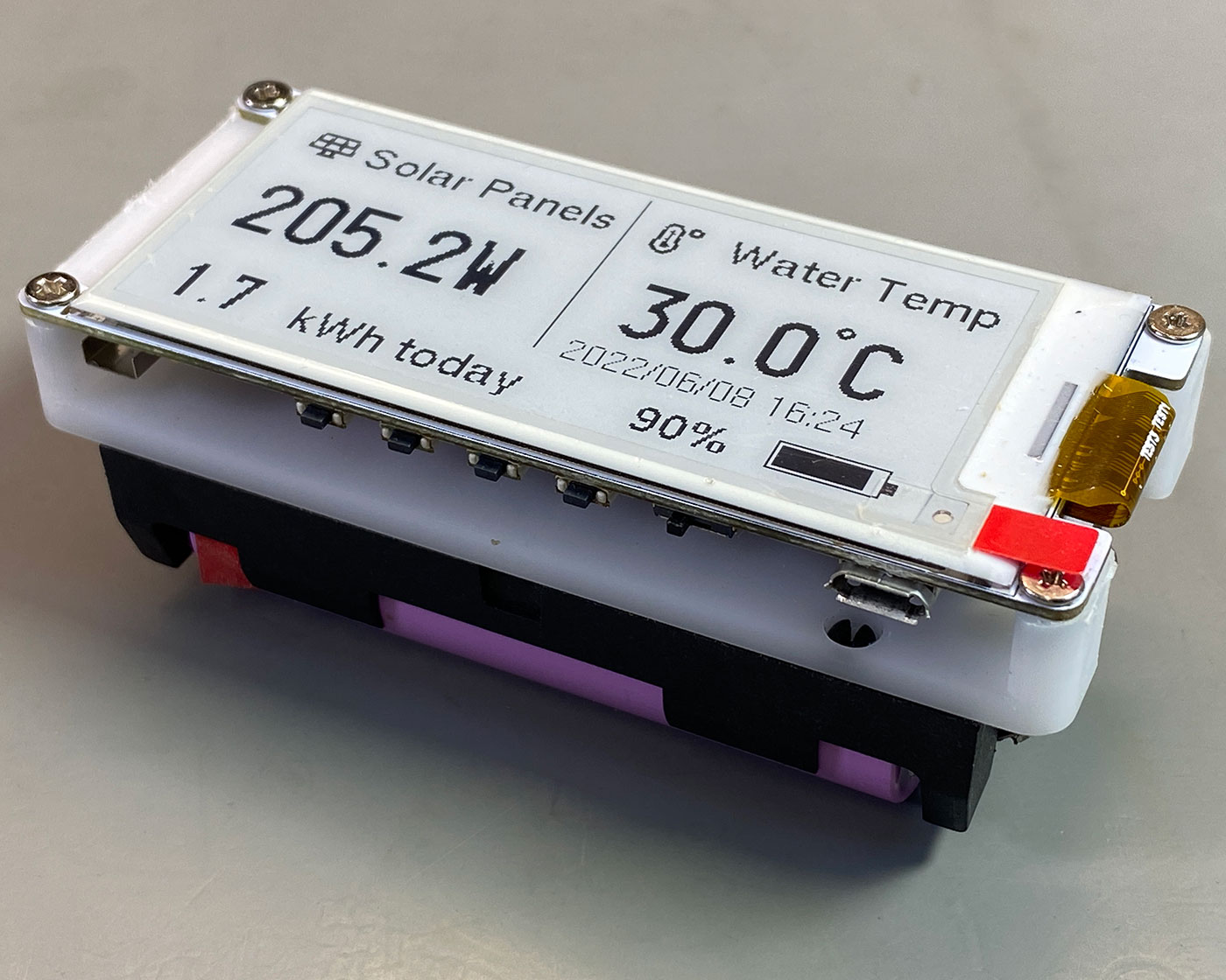
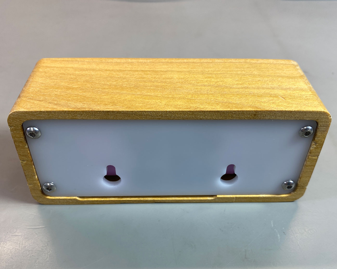
Building a Case
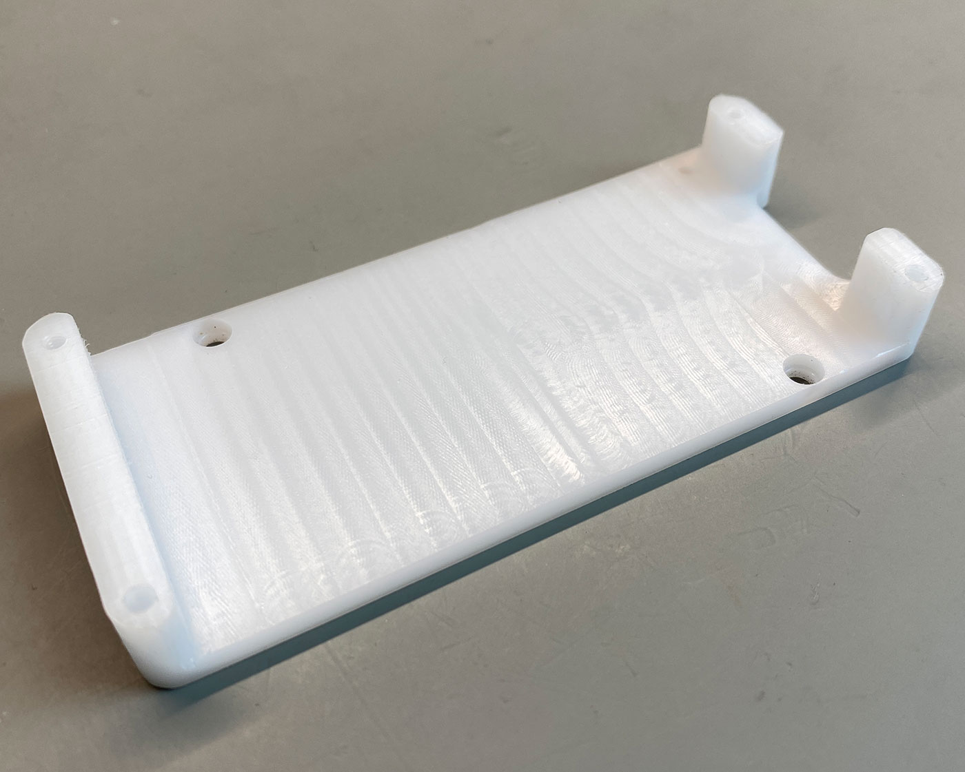
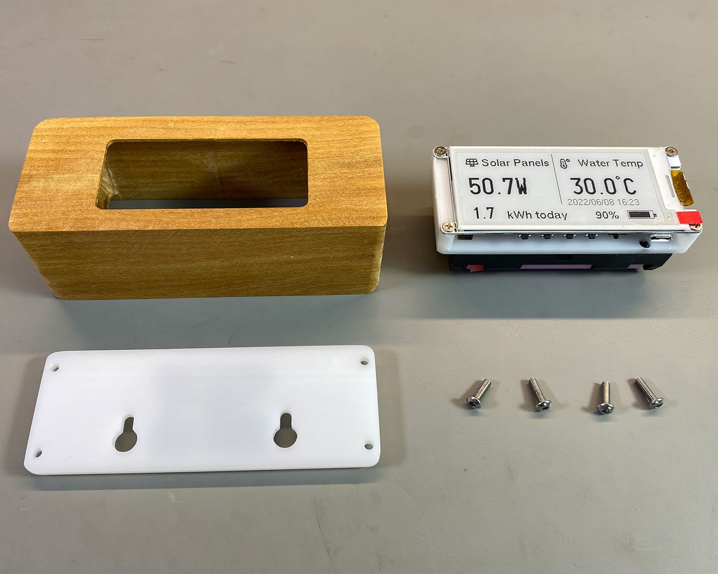
To hold the display PCB and battery holders, we used a 10mm thick sheet of Acetal plastic and machined this on our CNC mill to have four mounting holes for the screen and holes for the battery holder to clip into. We also added two M3 bolt holes to secure the battery holder.
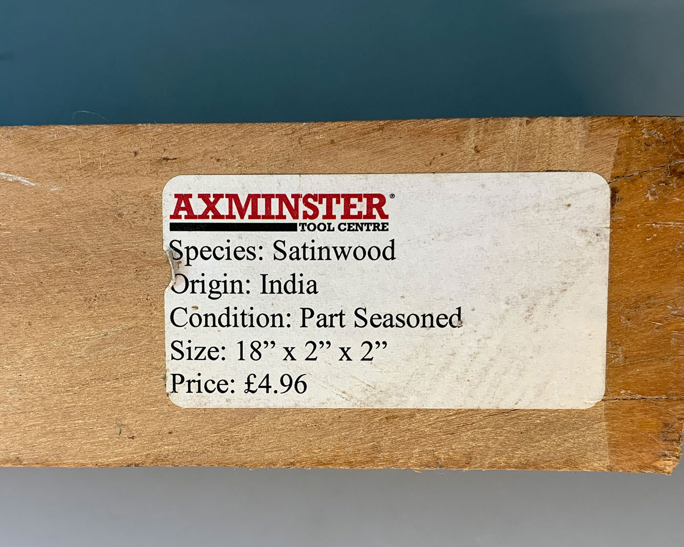
To build the outer case, we used a 50mm square section of India Satinwood, a tropical hardwood we purchased from Axminster Tools ( https://www.axminstertools.com/) around 15 years ago for a project which was never completed.
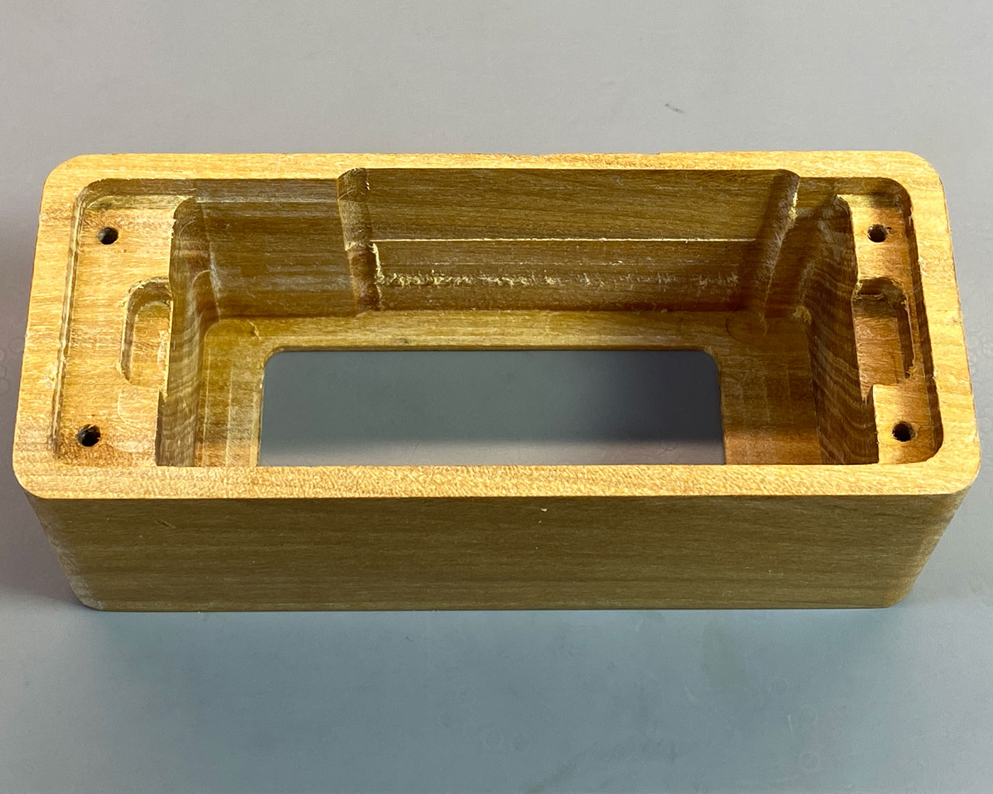
This wood has a very fine grain and is machined easily on the CNC mill to cut an inside pocket for the circuit board and batteries with a 2mm thick bezel around the edges of the ePaper display.
We cut a sheet of 3mm thick white acrylic for the rear panel, which was held in place using four M3 bolts. These can be easily removed for charging the batteries when needed.
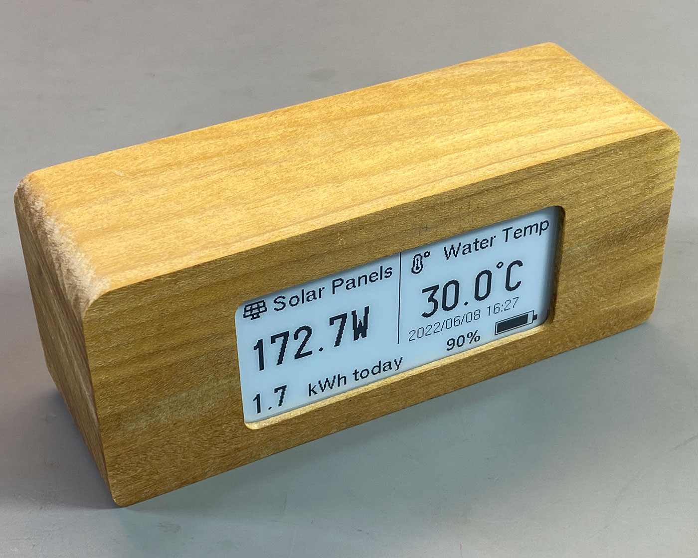
The wood was then polished with beeswax to provide a durable finish.


Russell
Hi, I purchaed the module to build this, however I have some questions:
1.”install dependencies”. What’s a dependency; is that like a DLL file? Where am I installing them; into my windows Pc or my Raspberry Pi home assistant, or onto the screen.
2. I am not using an Arduino. How do I do this with a PC? So far everything I do on my HA is via the web interface.
3. How do I load stuff onto the module/screen? It has usb, so I want to just plug it in and somehow copy across stuff but it doesn’t show up on the file explorer.
This is one of those things that a lot is assumed to be known, but whilst I’m not new to electronics at all, with these modules with serial, usb, wifi and Bluetooth connectivity, some things need to be specified. Ideally I’d like to just install your programme and it works.
Brian
Thank you for your comments, regarding your questions:
1.”install dependencies”. What’s a dependency; is that like a DLL file? Where am I installing them; into my windows Pc or my Raspberry Pi home assistant, or onto the screen.
The dependencies are: Adafruit-GFX-Library, lewisxhe/fork/GxEPD, debsahu/HARestAPI, ArduinoJson
The links above need to be downloaded into your Arduino libraries folder, This is normally in your documents folder on a Windows Computer
2. I am not using an Arduino. How do I do this with a PC? So far everything I do on my HA is via the web interface.
You need to install the Arduino IDE from https://www.arduino.cc/en/software
3. How do I load stuff onto the module/screen? It has usb, so I want to just plug it in and somehow copy across stuff but it doesn’t show up on the file explorer.
You need to modify the code to include the sensor data from Home Assistant then compile the code and upload to the eink module. You cannot drag and drop to the module.