Following the Echo Dot 3rd Gen Smart speaker Teardown post we have been exploring how the Echo Dot works and if it is possible to connect it to a computer to replace the firmware or install third-party applications.
The first step was to make some high-resolution photographs of the PCBs to aid in analysing the inner workings of the Echo Dot. There are two PCBs inside the Echo Dot which we will call the base board and the top board. The designers at Amazon were very kind to include lots of test points on both PCBs which greatly aided in reverse engineering their functions.
Top Board
The top board contains the components for audio input, LED output and wireless communication.
The top side of the top board contains four push switches, 2 LEDs and a light sensor.
At the centre of the board is a MediaTek MT7658CSN dual-band Wi-Fi and Bluetooth controller. This controller is designed to be paired with the main CPU and communicates with the outside world.
There are 12 RGB LEDs around the outside edge of the board, these are controlled using an ISSI IS31FL3236 36-channel LED driver. The IS31FL3236 is controlled using an I2C bus.
Four microphones, part number UY19 2W07, connect to two Texas Instruments TLV320ADC3101 ADCs. The TLV320ADC3101 is a stereo ADC designed for audio applications and contains a built-in DSP. The TLV320ADC3101 communicates with the CPU using an I2C and I2S bus. I2C is used to configure the ADCs on start-up and the audio stream is sent along the I2S bus.
There is a Fairchild 74LCX74 dual Flip-Flop on the PCB. When we wrote the original teardown blog post we speculated that the 74LCX74 is used for disabling the microphones. This was partially confirmed as driving pin 11 (Clock Pulse Input 2) high turns on the red LED ring to indicate that the microphone is disabled.
How the Echo goes about disabling the microphones themselves is still unknown as the ADCs do not contain an enable pin and we could not find any way of disabling the microphones electronically so the control of the microphones is most likely software based which opens up the possibility of listening to the microphones even when the user believes they are disabled.
There are three other ICs on the board marked UY96O, L12 and DJ4. Their purpose is currently unknown.
A 39-pin flat flex cable joins the top board to the base board. The cable carries data and power between the two boards. Most of the pins on the cable have corresponding test points so with a fast-enough logic analyser it should be possible to monitor the communication between the CPU and wireless controller.
There are several ground tags which connect to the metal chassis when the board is screwed into place.
The top board contains 89 test points. After lots of probing with a multimeter and oscilloscope, we were able to determine the purpose of many of the test points. The table below shows a list of the test points and their purpose.
| Test Point | Voltage | Device Connection | Notes |
| TM1 | D21 - 74LCX74 - Pin 4 | SD1 - Direct Set Inputs | |
| TM2 | Connector - Pin 35 | ||
| TM3 | GND | Ground | |
| TM4 | 3.3V | LEDs blink red when measured with a multimeter | |
| TM5 | 1.8V | Connects to TM47 via a resistor | |
| TM6 | 1.8V | ||
| TM7 | U2 - TLV320ADC3101 - Pin 17 | I2C serial clock 100KHz | |
| TM8 | U15 - UP9HD - Pin 4? | ||
| TM9 | GND | Ground | |
| TM10 | U2 - TLV320ADC3101 - Pin 18 | I2C serial data input/output | |
| TM11 | 3.3V | Power for CPU | |
| TM12 | GND | Ground | |
| TM13 | U4 - TLV320ADC3101 - Pin 4 | Reset | |
| TM14 | DS01 - RGB LED | ||
| TM15 | DS02 - RGB LED | ||
| TM16 | U2 - TLV320ADC3101 - Pin 2 | Audio serial data bus word clock (input/output) | |
| TM17 | DS01 - RGB LED | ||
| TM18 | DS02 - RGB LED | ||
| TM19 | U2 - TLV320ADC3101 - Pin 1 | Audio serial data bus bit clock (input/output) | |
| TM20 | DS01 - RGB LED | ||
| TM21 | DS02 - RGB LED | ||
| TM22 | U6 - UY96D - Pin 4 | Coupled via a resistor | |
| TM23 | Connects to TH45 via 10K resistor | ||
| TM24 | GND | Ground | |
| TM25 | Connector - Pin 31 | ||
| TM27 | U6 - UY96D - Pin 5 | ||
| TM28 | GND | Ground | |
| TM29 | U7 - IS31FL3236 - Pin 5 | OUT 7 | |
| TM30 | U7 - IS31FL3236 - Pin 8 | OUT 10 | |
| TM31 | U7 - IS31FL3236 - Pin 6 | OUT 8 | |
| TM32 | U7 - IS31FL3236 - Pin 9 | OUT 11 | |
| TM34 | U7 - IS31FL3236 - Pin 7 | OUT 9 | |
| TM35 | DS04 - RGB LED | ||
| TM36 | GND | Ground | |
| TM39 | U7 - IS31FL3236 - Pin 11 | OUT 13 | |
| TM40 | DS06 - RGB LED | ||
| TM41 | U7 - IS31FL3236 - Pin 12 | OUT 14 | |
| TM42 | DS06 - RGB LED | ||
| TM43 | U7 - IS31FL3236 - Pin 13 | OUT 15 | |
| TM44 | DS06 - RGB LED | ||
| TM45 | |||
| TM45 | Connector - Pin 31 via 1K resistor | ||
| TM47 | Connects to TM5 via a resistor | ||
| TM50 | Connector - Pin 30 | ||
| TM51 | GND | Ground | |
| TM52 | GND | Ground | |
| TM53 | Q3 | Coupled via a resistor | |
| TM56 | U22 - L12 | Coupled via a resistor | |
| TM57 | GND | Ground | |
| TM58 | Connector - Pin 1 | ||
| TM59 | GND | Ground | |
| TM61 | Q3 | ||
| TM62 | U7 - IS31FL3236 - Pin 36 | Shut down the chip when pulled low. | |
| TM63 | Connector - Pin 11 | ||
| TM76 | U4 - TLV320ADC3101 - Pin 8 | Capacitive Coupled - Mic or line analog input (left-channel single-ended or differential plus, or right channel) | |
| TM77 | U4 - TLV320ADC3101 - Pin 11 | Capacitive Coupled - Mic or line analog input (left-channel single-ended or differential minus, or left channel) | |
| TM79 | Connector - Pin 9 | ||
| TM80 | Connector - Pin 7 | ||
| TM81 | Connector - Pin 5 | ||
| TM82 | Connector - Pin 3 | ||
| TM83 | GND | Ground | |
| TM84 | DS07 - RGB LED | ||
| TM85 | DS08 - RGB LED | ||
| TM86 | DS07 - RGB LED | ||
| TM87 | DS08 - RGB LED | ||
| TM88 | DS07 - RGB LED | ||
| TM89 | DS08 - RGB LED | ||
| TM90 | DS09 - RGB LED | ||
| TM91 | DS10 - RGB LED | ||
| TM92 | DS09 - RGB LED | ||
| TM93 | DS10 - RGB LED | ||
| TM94 | DS09 - RGB LED | ||
| TM95 | DS10 - RGB LED | ||
| TM96 | DS11 - RGB LED | ||
| TM97 | DS12 - RGB LED | ||
| TM98 | DS11 - RGB LED | ||
| TM99 | DS12 - RGB LED | ||
| TM100 | DS11 - RGB LED | ||
| TM101 | DS12 - RGB LED | ||
| TM102 | Connector - Pin 10 | ||
| TM103 | Connector - Pin 13 | ||
| TM104 | Connector - Pin 15 | ||
| TM105 | Connector - Pin 17 | ||
| TM106 | Connector - Pin 19 | ||
| TM107 | Connector - Pin 2 | ||
| TM108 | Connector - Pin 4 | ||
| TP7 | U6 - UY96D - Pin 2 | ||
| TP9 | GND | Ground |
Logic Analyser connected to the test pins.
Two of the test points TM7 and TM11 connect to the I2C pins on the ADC U2 so we connected them to a logic analyser to see what data is being sent down the I2C bus.
The CPU tries to communicate with five devices on the I2C bus.
0x30 and 0x34 are the two ADC chips.
0x72 is unknown but a guess would be the light sensor on the top of the board as this is the only device which is read from as well as written to.
0x7E is the LED driver. The CPU sends a constant stream of packets to the LED driver while the device is powered.
0x88 The CPU sends a write packet to this address about 5 seconds into the boot process but does not receive a reply so this could be a device which was omitted from the final design, but the firmware was not updated to reflect this.
Base Board
The base board contains the main CPU, a Mediatek MT8516BAAA. We couldn’t find much about the MT8516 apart from a few short notes on Mediatek's website. What we do know is that it contains a quad-core, 64-bit ARM® Cortex-A35 core which operates at up to 1.3 GHz.
Next to the CPU is a Samsung KMFN60012M-B214 which contains 8Gb of eMMC flash memory and 1Gb of LPDDR3 ram.
A Texas Instruments TAS2770 audio driver provides the amplification for the internal speaker. The speaker connects to the baseboard via two sprung pins.
The rest of the baseboard is dedicated to power regulation with several linear and switching regulators.
The back of the baseboard contains 28 test points. Most of these are dedicated to the outputs from the voltage regulators but two test points caught our attention.
| Test Point | Voltage | Device Connection |
| TM1 | GND | |
| TM3 | GND | |
| TM4 | 0V | USB Debug |
| TM5 | 3.49V | USB Debug |
| TM6 | 1.9V | |
| TM33 | GND | |
| TM35 | 4V | |
| TM36 | 1.3V | |
| TM37 | 1.9V | |
| TM38 | 3.5V | |
| TM39 | GND | |
| TM40 | 1.3V | |
| TM41 | 2.1V | |
| TM42 | 3.1V | Voltage regulator test point |
| TM43 | 1.9V | |
| TM49 | 0V | |
| TM50 | 0V | |
| TM51 | 12V | |
| TM52 | 12V | |
| TM53 | GND | |
| TM54 | 1.9V | |
| TM55 | 12V | |
| TM56 | 1.9V | |
| TM57 | Audio Out | |
| TM58 | Audio Out | |
| TM59 | 1.9V | |
| TM60 | 1.9V |
At the bottom of the plastic enclosure is a small rectangular hole with 6 test points visible on the baseboard. Four of the test points are related to power with 12V, 1.9V and two ground pins. Two of the test points TM4 and TM5 connect to a pair of traces that looked suspiciously like a differential pair and probing them showed that TM4 was 0V and TM5 was 3.49V. These are the voltages found on the data lines of a USB cable and previous versions of the Echo have included a USB port for firmware updates, so it stood to reason that these two pins were connected to a USB interface.
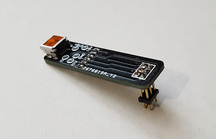
The test points are spaced on a 2mm 3x2 grid so we soldered a 2mm pitched connector onto the test pins and designed a small PCB which would connect the pins to a micro USB socket. As there was already a hole in the base of the case, we could connect the new USB interface to the Echo Dot when it is assembled. When we designed the PCB we were not 100% sure whether the USB traces were the correct way around or if the 1.9V pin was used for anything else so we added a row of 0R resistors between the USB socket and the header pins so we would be able to link the pins in any combination with jumper wires if necessary.
After waiting several weeks for the PCB to arrive from China we assembled the new USB adapter and connected it to an old sacrificial netbook that we keep around for plugging in unknown USB devices. If we got something wrong, we didn’t want to destroy the USB interfaces on our workstations.
The new debug header to the USB board.
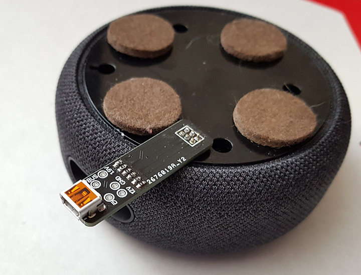
Debug adapter fitted to the base of the Echo Dot with extra padded feet stuck onto the case to give clearance for the PCB.
Running the Linux command “lsusb -v” gave us a list of USB devices connected to the netbook and in the list was a Mediatek device with the following details.
Bus 001 Device 006: ID 0e8d:2008 MediaTek Inc.
Device Descriptor:
  bLength                18
  bDescriptorType         1
  bcdUSB               2.00
  bDeviceClass            0
  bDeviceSubClass         0
  bDeviceProtocol         0
  bMaxPacketSize0        64
  idVendor           0x0e8d MediaTek Inc.
  idProduct          0x2008
  bcdDevice           ff.ff
  iManufacturer           3 MediaTek
  iProduct                4 AEODN
  iSerial                 5 XXXXXXXXXXXX
  bNumConfigurations      1
  Configuration Descriptor:
    bLength                 9
    bDescriptorType         2
    wTotalLength       0x0027
    bNumInterfaces          1
    bConfigurationValue     1
    iConfiguration          0
    bmAttributes         0xc0
      Self Powered
    MaxPower              500mA
    Interface Descriptor:
      bLength                 9
      bDescriptorType         4
      bInterfaceNumber        0
      bAlternateSetting       0
      bNumEndpoints           3
      bInterfaceClass       255 Vendor Specific Class
      bInterfaceSubClass    255 Vendor Specific Subclass
      bInterfaceProtocol      0
      iInterface             17 MTP
      Endpoint Descriptor:
        bLength                 7
        bDescriptorType         5
        bEndpointAddress     0x81  EP 1 IN
        bmAttributes            2
          Transfer Type            Bulk
          Synch Type               None
          Usage Type               Data
        wMaxPacketSize     0x0200  1x 512 bytes
        bInterval               0
      Endpoint Descriptor:
        bLength                 7
        bDescriptorType         5
        bEndpointAddress     0x01  EP 1 OUT
        bmAttributes            2
          Transfer Type            Bulk
          Synch Type               None
          Usage Type               Data
        wMaxPacketSize     0x0200  1x 512 bytes
        bInterval               0
      Endpoint Descriptor:
        bLength                 7
        bDescriptorType         5
        bEndpointAddress     0x82  EP 2 IN
        bmAttributes            3
          Transfer Type            Interrupt
          Synch Type               None
          Usage Type               Data
        wMaxPacketSize     0x001c  1x 28 bytes
        bInterval               6
Device Qualifier (for other device speed):
  bLength                10
  bDescriptorType         6
  bcdUSB               2.00
  bDeviceClass            0
  bDeviceSubClass         0
  bDeviceProtocol         0
  bMaxPacketSize0        64
  bNumConfigurations      1
Device Status:     0x0001
  Self Powered
As suspected the test points are a USB interface for flashing the firmware on the Echo Dot. We found some software for flashing MediaTek devices but quickly realised that the software needs a scatter file which is similar to a partition table and contains the information needed for the software to read and write to the MediaTek processor.
Searches online for a scatter file for an MT8516 gave us no results but we did find a reference to booting the Echo into fastboot mode by holding down one of the buttons on startup. After a bit of experimenting, we found that holding down the button with the white dot while turning on the device boots the Echo into fastboot mode and turns the LED ring green.
Running the command "fastboot getvar all" returned the following:
root@echodev:~$ fastboot getvar all > fastboot.txt
(bootloader) 	antirback_tee_version: 0x0001
(bootloader) 	antirback_lk_version: 0x0001
(bootloader) 	antirback_pl_version: 0x0001
(bootloader) 	rpmb_state: 1
(bootloader) 	lk_build_desc: 09a5edd-20190510_065840
(bootloader) 	pl_build_desc: 2b7c882-20190510_065840
(bootloader) 	secure: yes
(bootloader) 	prod: 1
(bootloader) 	unlock_status: false
(bootloader) 	tu_code: q/3z6mhb4gVE0G9ed5H6QkQrlEwMEdyiotGFiQJa/wM=
(bootloader) 	unlock_code: xxxxxxxxxxxxx
(bootloader) 	serialno: xxxxxxxxxxxxxx
(bootloader) 	max-download-size: 0x8000000
(bootloader) 	kernel: lk
(bootloader) 	product: DONUT
(bootloader) 	version-preloader: 0.1.00
(bootloader) 	version: 0.5
all: Done!
Fastboot can see the device but as the bootloader is locked we can not extract or update the firmware image, so for the moment we have come to a dead end. Hopefully, someone else will have more luck with accessing the Echo Dots firmware.
PCB Files
You can download the USB adapter PCB files in Diptrace format and also the Gerber files from this link.


Hal
I want to add a 'Wi-Fi active' led into my Echo Dot to show if it is communicating. Would this be an easy addition? Which lines would I need to pick up?
Alan Campbell
can I use a simple sound jack from my TV to my dot
Brian
Alan, the audio out on the dot is a 3.5mm connection and if your TV has a 3.5mm input it should work,
Hal, I am not sure if there are any datalines which show when the Wi-Fi is active on the Dot. I think it is communicating with the Amazon servers all the time.
Jose Torres
Great post. I wanted to bring attention and hopefully clarify that the Gb when referring to the Samsung EMCP part should actually be 1 GB since in fact that part contains 8Gb of RAM. Here's a link to that part on Samsung's website: https://www.samsung.com/semiconductor/mcp/KMFN60012M-B214/
Jon Smirl
It is running FireOS. Check if adb works.
Brian
Jon, we did try adb but the bootloader is locked so we couldn't extract or replace the OS image.
Frank
I can see
(bootloader) product: DONUT
in your fastboot output.
Is my assumption true that the programmed fireOS on these devices is based on Android Donut (1.6)?
Evan
Thanks for the blog posts, Brian. I'm digging into my echo 3rd gen as well, and found that my MCP, combined flash and ram module, is a Micron jz099 9fa97. Everything else is the same, even the traces look the same as yours. This part must have a standardized pinout and voltage/timing. Do you know anything about the interface? is it emmc? ufs? 3.3v or 1.8 (for flash)? I haven't been able to get a datasheet yet.
thanks again!
Brian
Evan, We are not sure what the interface is as we have not been able to find any datasheets.
zeptobars
hey glad to see there is someone who is digging deeper into to the v3 of the echo dot. Similar results got https://medium.com/@micaksica on the v2. The scatter file seems to be a critical point.
Could the soc got a relabel for amazon so the real soc-name is not known ?
Another point could be the similarity towards the amazon tablets ?
thanks for your work
Evan
I found an equivalent datasheet, by searching MT29TZZZ8D5JKEZB-107 on micron.com with a free account. Pretty sure the pinout is standardized across these emmc mcp chips. Pinout: https://ptpimg.me/ur66pp.png
Sascha
Did you do any logic sniffing on i2c bus?
Orion
I didn't find any mention of the j22 SMD pads. I think this is a connector for the optional led display which shows the time. Is this correct? Also, I was wondering if it was possible to wire an HDMI to the Alexa since the processor is technically capable of outputting an image through HDMI.
Markus
Where is the (stereo) signal for the audio output jack is coming from? Is there an additional DAC Chip, as the TAS2770 is a mono amplifier and I can see no output pins others than that for the speaker?
user154
For the most part this article is beyond my scope of knowledge, but have you tried using a tool like miraclebox that is able to dump the firmware and create the scatter file of MTK phones using the USB VCOM mode that the flash tools use?
Pats
Hi, Can this USB adapter power the Echo Dot 3 using battery bank ? If yes, then can the FTD1232 USB adapter used ?
Thanks
Ilya
Have you tried creating a scatter file with MTK droid tools? More details here: https://sites.google.com/site/tweakradje/android/flashing?tmpl=%2Fsystem%2Fapp%2Ftemplates%2Fprint%2F&showPrintDialog=1
Marius
That's a great article. Thank you. I am looking for the opportunity to transform my echo dot into a subwoofer recognised as Echo Sub. Echo dots are cheap, Echo Subs not. So my idea is to connect my analogue subwoofer to the fake Echo Sub and create a set like 2 Echo Dots + Echo Sub. Do you have any idea how to trick the system to recignise Echo Dot as the Echo Sub.
Greetings.
Nico
umt could unlock the bootloader, has news, I have one blocked here
Leinad
Did anyone have any success with that? I did order a few cheap echo dots 3 and would love to run Ubuntu or something on them.
Leinad
Also, did anyone look into booting from an sd card?
Maybe there are once again pins to wire up an adapter and boot from an sd card...
oliver
0x88 is probably the LCD, and as it can't read from it, it knows not to send data towards it?
Did you have any luck finding the TX/RX of the mediatek CPU? You'd only really spot them with a scope, as on idle the TX would be at 1v8 or 3v3 and the RX at 0v ...
Kevin
Here they are using libmtp to access the same Mediatek device like you above:
idVendor=0e8d, idProduct=2008
https://sourceforge.net/p/libmtp/bugs/1422/
So probably not usable for flashing, just for playing music.
Andrew P
Excellent article, Brian. I am looking to figure out all the test points for the Echo Dot 2nd gen. Do you have any advice for determining what all the test points do? I currently only have a multimeter, not an oscilloscope, so that will limit some of my detective work.
Brian
Andrew, If you don't have a oscilloscope you can use the multimeter to measure the voltages on each pad which will allow you to determine if they are fixed voltages or are datalines which can be at a lower voltage level if your multimeter averages the readings.
Bruno M
Hello, I have a 3rd gen echo that I have been poking around. However, the PCB is definetely different from yours (haven't checked the revision). On mine, the test points are numbered differently, but on what looks like TM59 on you pictures (thats TM45 for me), is an UART TX pin for the CPU. On boot, depending on whether you hold the dot button or not it briefly spits out standard mediatek stuff at 115200 baud, then it switches to 921600 baud and you can see the preloader doing its work, then the kernel boots up (only if not going into fastboot). Fastboot boot https://pastebin.com/qvLqKd3Y Normal boot https://pastebin.com/ytniyhJM .
I initially suspected that the nearby test pad is the UART RX pin, but currently I don't have the means to level shift to 1.8V for testing. Also, note that right after completing the boot, the kernel switches the console to another UART. See the interesting notice about using a debug build in the boot log.
Kickhad
I'm thinking of using the top board with a Raspi and Mycroft.
Anyone have thoughts? The mic inputs are attractive.
Tim
I would like to solder a section of individual LED Strip to each of the 12 LED's around the ring. Which pins am I supposed to go to for each LED?
Thomas
Would it not be easy to read/write the memory chip? So unlock/replace the bootloader can be done?
Kyle
@Kickhad, I was looking into doing the same thing. It looks like an rpi zero 2 would fit in the enclosure if the Base board were removed, and I'm curious if the rpi could take over the that role. It would require a breakout board for the 39-pin FPC connector and a 5v buck converter, but those both seem achievable. Any idea if this is possible or worth pursuing?
My motivation is to create a Picroft based voice assistant using the echo hardware. Right now I can buy an echo dot 3rd gen for $15, which, for the money, is hard to beat.
Replacing the bootloader sounds like the better option if it's possible, but it doesn't seem like there has been much progress on this in a while.
Tom
I got a 3rd Gen from pawn, it's registered to PO. I'd like to use it just as speaker hooked up though aux, thinking rewire aux out jack. Is there an easy way to input analog through dac into the amp so it will just play whatever is plugged in? Assuming mic inputs are analog. Could I wire input in there, just disconnect mics, then feed digital from dac into amp?
William
Great job.. Very informative..
What points would I test to see why my echo dot is not turning on?
Brian
I would check the test points around the power connection to ensure that the voltage is reaching the board.
A guy
Can I order a pre assembled usb breakout board for echo dot 3
Oswaldo
No puedo vincular Alexa tercera generación a la red de wifi, la app de mi dispositivo móvil no la reconoce. Que podría ser la causa? Otro dato el aro de luz azul o naranja dependiendo de la función, en un fragmento se torna roja, esta luz me indica algún error o fallo en el dispositivo?
I cannot link Alexa third generation to the Wi-Fi network, the app on my mobile device does not recognize it. What could be the cause? Another piece of information, the blue or orange light ring depending on the function, in a fragment it turns red. Does this light indicate an error or failure in the device?