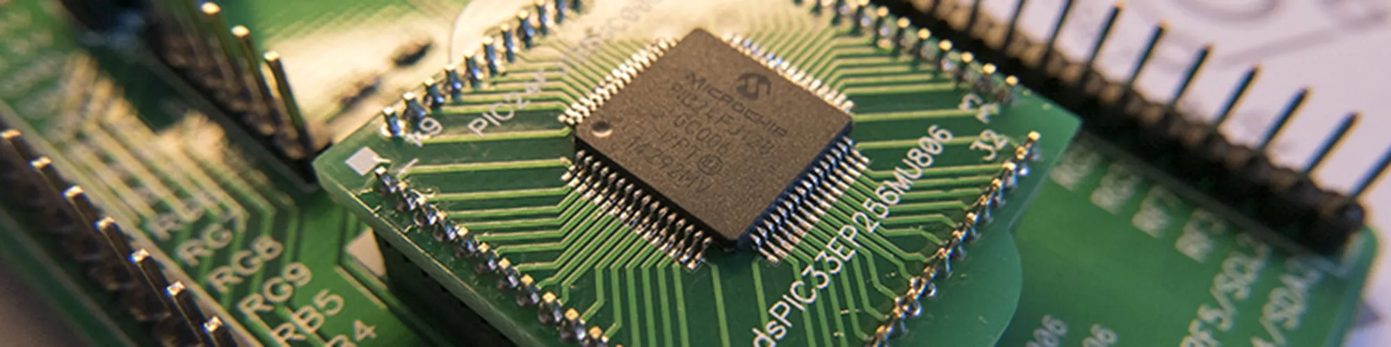
Several of our recent projects have used a 16 bit PIC24 microcontroller from Microchip. The PIC24FJ128GC006 contains two 16-bit ADC channels which makes it useful for measuring voltages more accurately than the 10 or 12 bit ADCs you normally find on microcontrollers. We used this microcontroller for the temperature controller on our recent Soldering Robot and are looking at using it for another project in the future.
One problem we found was trying to prototype code using this microcontroller as unlike Arduino and any ARM microcontrollers there isn’t a small easy-to-use prototyping board available for the PIC24 chip. Microchip makes an Explorer 16 Development Board which is designed to work with the PIC24 microcontrollers but it is large and fairly expensive and is designed to work best with other Microchip add-on cards.
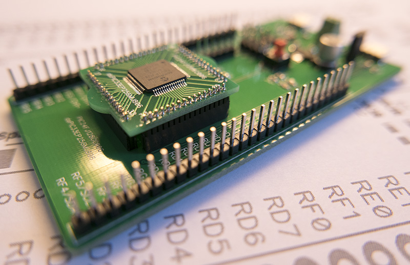
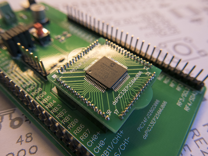
With this problem in mind, we decided to design and build a small prototyping board that would work with the PIC24FJ128GC006 as well as one of Microchips DSPIC33EP256MU806 dsPIC series microcontrollers.
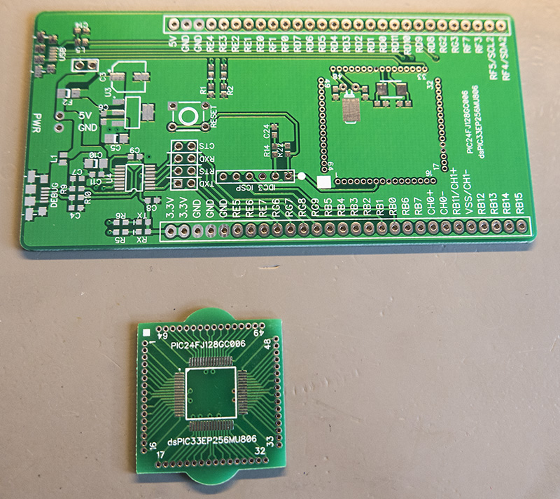
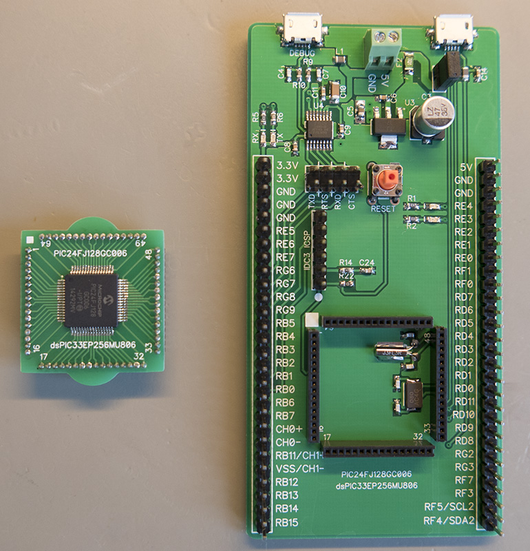
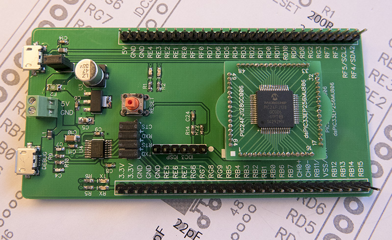
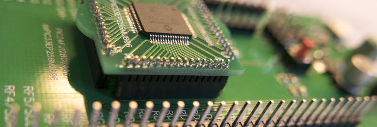
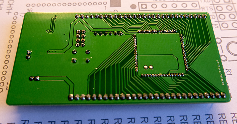
The prototyping board was designed with removable daughter boards for the microcontroller. This means that we can use several different microcontrollers on the same board and if we accidentally do something that damages a part of the microcontroller it is easy to replace it without having to unsolder the chip.
The PIC24FJ128GC006 includes a USB port so we added one onto the board, this will come in handy if we want to design any devices that act as a USB device or host. Programming of the board is done through an IDC header which connects to a Microchip MPLAB ICD 3 programmer.
To make debugging easier we decided to add a USB to UART chip using an FT230X from FTDI. This connects to one of the UART ports on the microcontroller and gives us the ability to send and receive serial commands like you can with the Arduino boards. The debug port can also be used to supply power to the board from the 5V USB bus which is then converted down to 3.3V using a linear regulator.
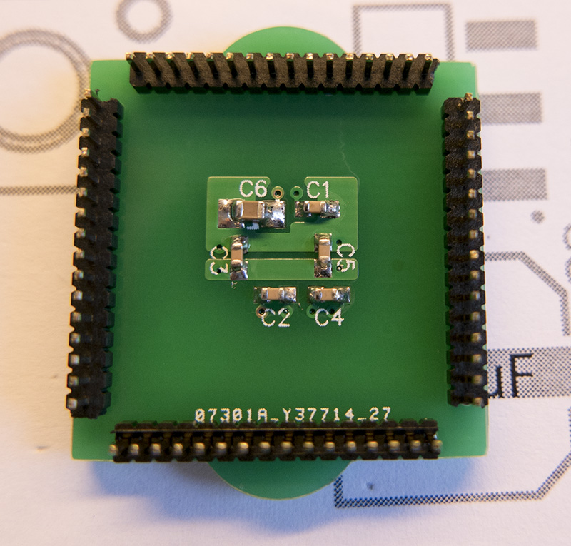
The daughter boards contain the microcontroller and the decoupling caps but we decided to put the crystals onto the main board. An 8MHz crystal was used for the primary oscillator and a 32.768Khz crystal was used for the secondary oscillator. This gives us the ability to design applications that can switch between the oscillators depending on the task saving which saves power. A pair of LEDs were added onto the board as well to be used as indicators.
We have uploaded the design files for the prototyping board and the MCU daughter board along with a basic firmware template which we created in the MPLAB Code Configurator to check the board was working correctly to our GitHub account at https://github.com/briandorey/PIC24-Dev-Board


liana
thanks for info