I was recently asked to help set up an AllStarLink Gateway using a Tait TM8110, a 25W PMR radio operating between 136MHz and 174MHz, making it ideal for 2M ham radio use.
AllStarLink is a network of Amateur Radio repeaters accessible to each other via Voice over Internet Protocol. AllStarLink runs on a dedicated computer you host at your home, radio site or computer centre, and it is based on the open-source Asterisk PBX system. You can read more about AllStarLink at www.allstarlink.org.
This project was very time-consuming and frustrating due to the lack of available documentation for the radio, with hardware and software issues causing many delays and setbacks.
Power and sound card hardware
The sound interface from the Raspberry Pi to the radio is a modified CM108-based USB sound card. Instructions for the modifications are on allstarsetup.com/how-to-modify-a-cm108-for-allstar. These are also available from eBay with the changes already completed to connect to your radio.
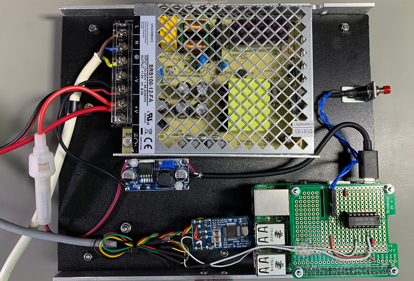
To power the radio and Raspberry Pi, I used a Multicomp Pro MP002000 AC/DC Enclosed Power Supply with 1 Output, 102 W, 12 V, 8.5 A
The Raspberry Pi required a 5-volt supply, and I used a DC to DC Converter 3.0-40V to 1.5-35V Buck Converter Adjustable Power Supply Module from Amazon which has a maximum output current of 3 amps.
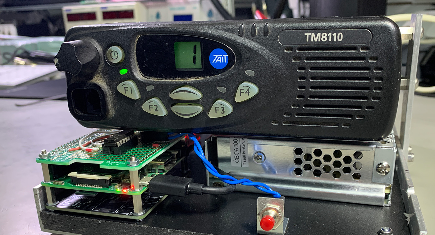
All the hardware was fitted to a plastic base with metal brackets to allow the radio to be mounted above, making a compact and easy-to-use setup.
Mains power consumption for the Raspberry Pi and radio with the radio transmitting on low power is 16W, receive mode is 4W.
Connecting the USB sound card
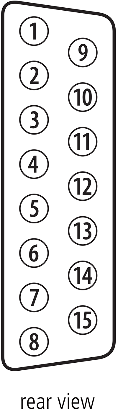
The modified CM108 sound card was connected to the radio via the rear panel DB15 connector; the wiring diagram below shows the connections required.
| DB 15 Pin | Wire Colour | Function | Signal Name |
|---|---|---|---|
| 2 | White | COS to hex inverter | AUX_GPIO5 |
| 7 | Black | Tx Audio | AUD_TAP_IN |
| 12 | Red | PTT | AUX_GPI1 |
| 13 | Yellow | Rx Audio | AUD_TAP_OUT |
| 15 | Green | GND | AGND |
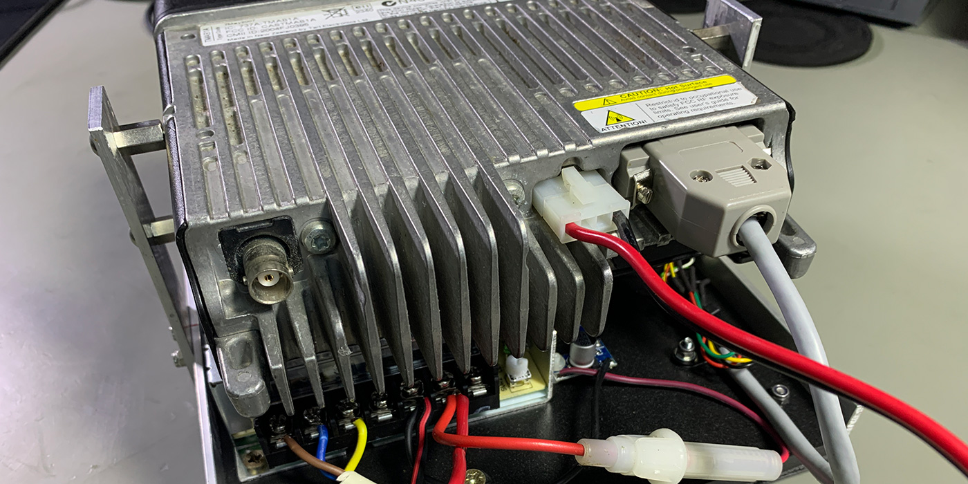
The following pin assignments are from the service manual for the Tait TM8110 radio.
| Pinout | Pin | Signal name | Description | Signal Type |
|---|---|---|---|---|
 |
12 | AUX_GPI1 | General purpose digital input. Programmable function. | Digital, 3V3 CMOS |
| 5 | AUX_GPI2 | General purpose digital input. Programmable function. With LK3 fitted, GPI2 is an emergency power sense input. | Digital, 3V3 CMOS | |
| 4 | AUX_GPI3 | General purpose digital input. Programmable function. With LK2 fitted, GPI3 is a power sense input | Digital, 3V3 CMOS | |
| 10 | AUX_GPIO4 | Programmable function and direction. Pads available to fit a higher power driver transistor on GPIO4 line | Digital, 3V3 CMOS input; open collector output with pullup | |
| 2 | AUX_GPIO5 | Programmable function and direction. Pads available to fit a higher power driver transistor on GPIO4 line | Digital, 3V3 CMOS input; open collector output with pullup | |
| 9 | AUX_GPIO6 | Programmable function and direction. Pads available to fit a higher power driver transistor on GPIO4 line | Digital, 3V3 CMOS input; open collector output with pullup | |
| 1 | AUX_GPIO7 | Programmable function and direction. Pads available to fit a higher power driver transistor on GPIO4 line | Digital, 3V3 CMOS input; open collector output with pullup | |
| 11 | AUX_TXD | Asynchronous serial port - Transmit data | Digital, 3V3 CMOS | |
| 3 | AUX_RXD | Asynchronous serial port - Receive data | Digital, 3V3 CMOS | |
| 7 | AUD_TAP_IN | Programmable tap point into the Rx or Tx audio chain. DC-coupled. | Analog | |
| 13 | AUD_TAP_OUT | Programmable tap point out of the Rx or Tx audio chain. DC-coupled. | Analog | |
| 14 | AUX_MIC_AUD | Auxiliary microphone input. Electret microphone biasing provided. Dynamic microphones are not supported. | Analog | |
| 6 | RSSI | Analog RSSI output. | Analog | |
| 8 | +13V8_SW | Switched 13.8V supply. Supply is switched off when radio body is switched off. | Power | |
| 15 | AGND | Analog ground | Ground |
IO Issues and solution
The COS input on the sound interface needed to be connected to a signal which is pulled to ground when a signal is received by the radio and contains the required CTCSS tone of 77.0 Hz.
I initially tried connecting this directly to the radio AUX_GPIO5 pin (Pin 2 on the connector) and configured the radio software as an Output and to set this LOW when in “Busy status” on the Action column.
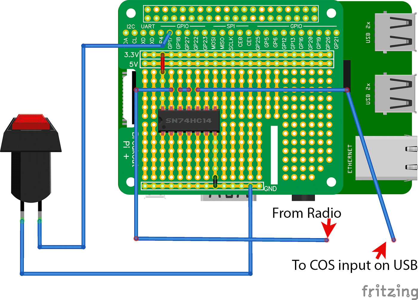
This did not work as expected, and after further investigation, I found that the radio and sound interface required a buffer chip to switch the signal levels.
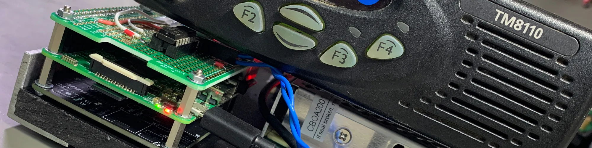
I found a DIP package SN74HC14 Hex Inverters with Schmitt-Trigger Inputs from Texas Instruments in our parts drawers and using a Breakout Pi Plus board a simple circuit was assembled to use two of the hex inverters connected in series as a non-inverting buffer to process the signal to the COS input on the USB sound card.
The image below shows the hex inverter circuit on the breakout development board with a power shutdown switch connected to GPIO 17. Shutdown via the button can be enabled in the Hamvoip software.
With the inverter added, the Hamvoip software was then able to show the busy status of the radio, but this was triggering with any received signal and not only valid transmissions with the CTCSS tone of 77.0 Hz.
Changing the action to “Signalling Audio Mute Status” resolved this issue.
Radio Programming and Setup
The radio is programmed via the front panel RJ45 connector or the rear panel DB15 connector. In a previous blog post, you can see how we made a USB Programming Cable for Tait TM8110 PMR Radios.
The radio programming software can be purchased from radiotronics.co.uk
The screenshots below show the software settings on the various settings pages and tabs, which were programmed into the radio via the USB programming cable.
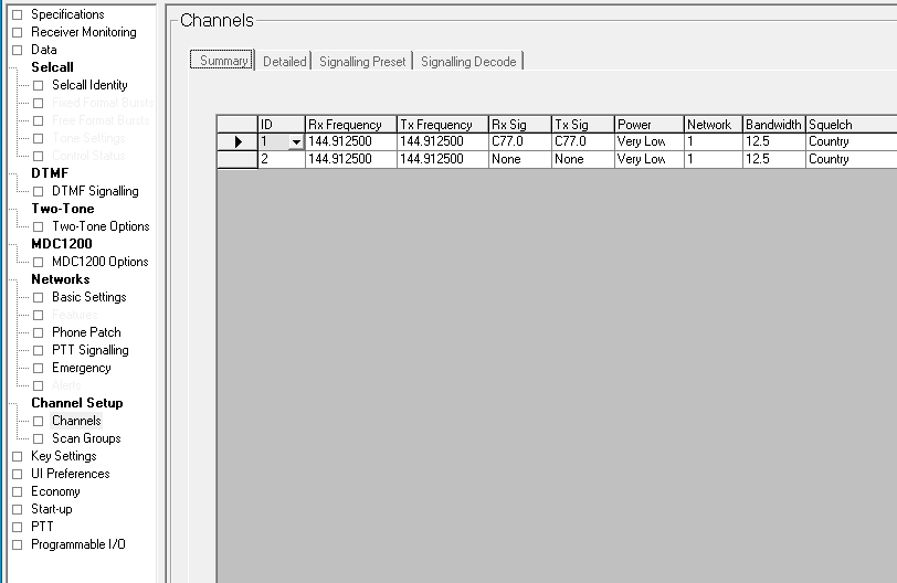
Channel Setup > Channels
This tab contains the TX and RX frequencies and required CTCSS tones in the Rx Sig and Tx Sig fields. The Squelch settings have the following options: Country, City and Hard. As the radio was used in a countryside location, this was set to Country. For testing, a second channel was added without the CTCSS tones, which was removed for the final programming.
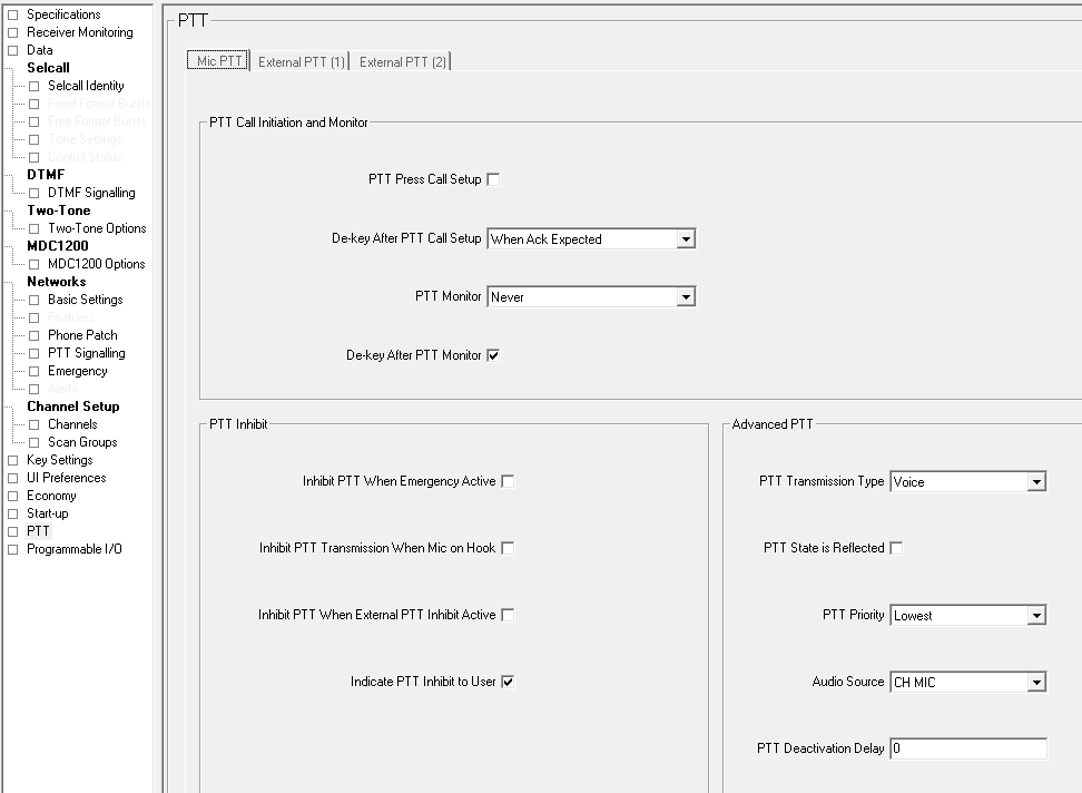
PTT > Mic PTT tab
This contains the PTT actions for the microphone input on the front panel. The PTT Priority should be set to Lowest for the rear External PTT to take priority.
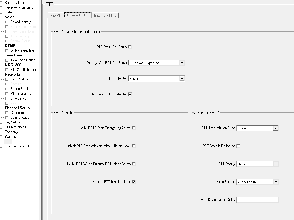
PTT > External PTT (1) tab
This contains the PTT actions for the external PTT pin via the rear DB15 connector. The following settings need to be changed under Advanced EPTT1:
- PTT Transmission Type: Voice
- PTT Priority: Highest
- Audio Source: Audio Tap In
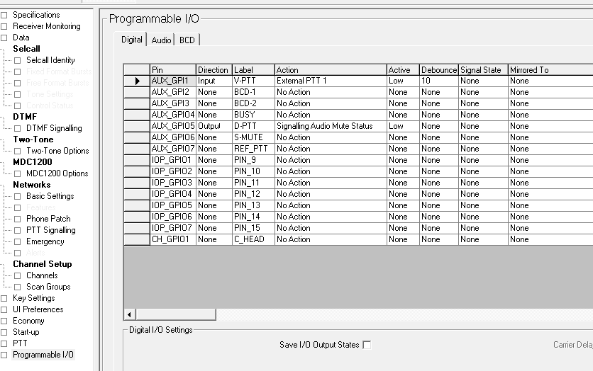
Programmable I/O > Digital tab
This contains the settings for the I/O pins on the rear DB15 connector. The following settings should be entered:
| Pin | Direction | Label | Action | Active | Debounce | Signal State | Mirrored To |
|---|---|---|---|---|---|---|---|
| AUX_GPI1 | Input | V_PTT | External PTT 1 | Low | 10 | None | None |
| AUX_GPIO5 | Output | D-PTT | Signalling Audio Mute Status | Low | None | None | None |
All other pins should be set as:
- Direction: None
- Action: No Action
- Active: None
- Debounce: None
- Signal State: None
- Mirrored To: None
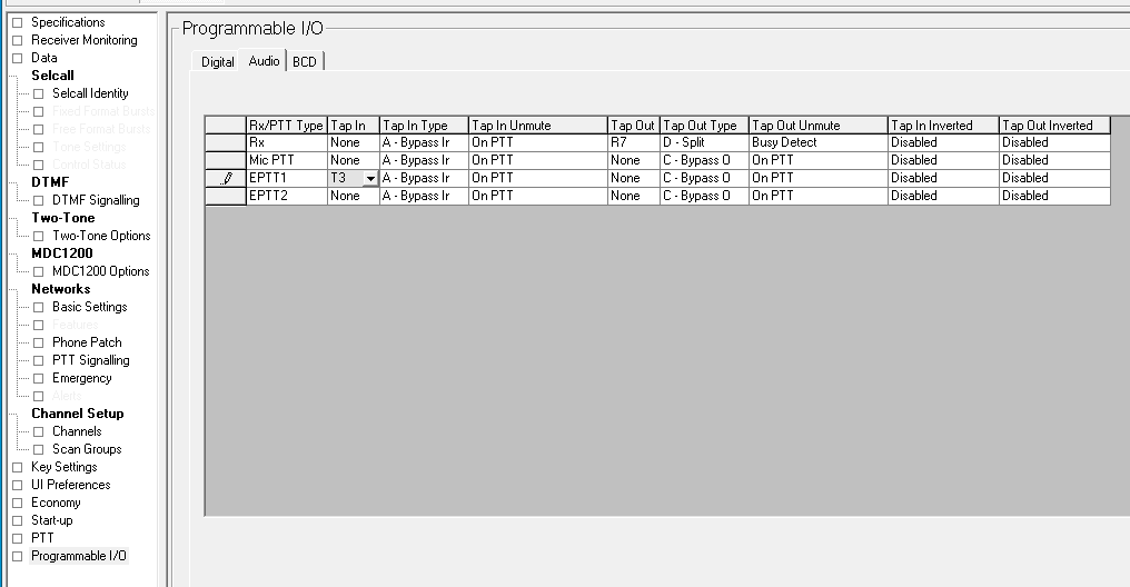
Programmable I/O > Audio tab
This contains audio input and output settings via the I/O pins on the rear DB15 connector. The following settings should be entered:
| Rx/PTT Type | Tap In | Tap In Type | Tap In Unmute | Tap Out | Tap Out Type | Tap Out Unmute | Tap In Inverted | Tap Out Inverted |
|---|---|---|---|---|---|---|---|---|
| Rx | None | A – Bypass Ir | On PTT | R7 | D-Split | Busy Detect | Disabled | Disabled |
| Mic PTT | None | A – Bypass Ir | On PTT | None | C-Bypass O | On PTT | Disabled | Disabled |
| EPTT1 | T3 | A – Bypass Ir | On PTT | None | C-Bypass O | On PTT | Disabled | Disabled |
| EPTT2 | None | A – Bypass Ir | On PTT | None | C-Bypass O | On PTT | Disabled | Disabled |
Raspberry Pi Software
The software used for the interface is HAMVOIP Asterisk Allstar for the Raspberry Pi 2/3/4 from https://hamvoip.org/
Setup instructions for the software are available to download from https://hamvoip.org/howto/config-setup.pdf
A micro-SD card with the Hamvoip software was supplied and configured by another local radio ham for the repeater. This should have functioned without any other changes apart from sound level adjustments. Still, after many hours of testing, I could not get the software to communicate with the radio and internet, and the WiFi on the Raspberry Pi refused to connect.
A second micro-SD card was tried with a different Hamvoip install, and this functioned correctly, and the software could be configured to work with the Tait radio.
Access to the settings is via an SSH connection on port 22 or your custom port. The radio announces its IP address on your local network when it starts.
Logging in via SSH shows the following menu:
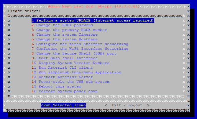
This menu allows you to select different options. To configure the sound settings, select 12 Run simpleusb-tune-menu Application, and this will load the following menu options:
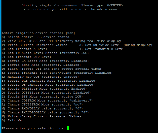
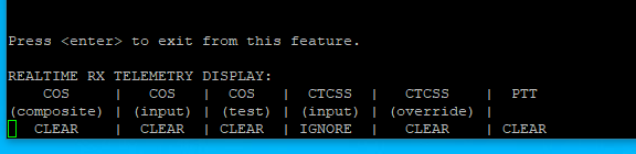
Selecting option “V” shows real-time data from the COS, CTCSS and PTT statuses. This is useful when debugging the communication between the radio and the COS input on the USB sound interface.
Selecting option 2 allows you to adjust the Rx sound level.
Selecting options 3 and 4 allows you to adjust the Tx sound level.
The “D” option sends a series of audio tones to the radio, which helps set the Tx levels.
Once the changes are complete, you must use the “W” option to save the current parameter values.
Restart the Raspberry Pi once complete, and the new AllStarLink Gateway should be active.
The completed system was installed and connected to an external antenna in Swanage, South Dorset, in the United Kingdom.
Accessing the MB7IPR Simplex Gateway
The Allstarlink gateway is an analogue gateway using the following frequency and settings:
Band: 2M
Input / Output frequency: 144.9125 MHz
CTCSS tone: 77.0 Hz
Narrow Deviation
Allstar Node no: 57622
ETCC Region: South-West
IARU Square: IO90
The following DTMF Macro commands are available to control the Gateway
| Code | Command | Notes |
|---|---|---|
| *70 | Gateway status | States any current connections |
| *73 | Disconnect | Please disconnect when you have finished |
| *51 | Connect to (2462) | WW7PSR Seattle Repeater Group |
| *52 | Connect to (29332) | Alaska Allstar Hub |
| *53 | Connect to (2560) | WIN System Hub Los Angeles |
| *54 | Connect to (2195) | Freestar |
| *55 | Connect to (41288) | Hubnet |
| *56 | Connect to (45225) | East Coast Reflector |
| *57 | Connect to (27225) | Philadelphia Hub |
| *58 | Connect to (525960) | W1SBW Ragchew Net |
| *59 | Connect to (40894) | Hubnet Parrot to check your audio levels |


Paul
Thanks so much for all your help, hopefully we can some sleep now we got the bugs out of the system. Paul G0vzy gateway keeper
Dave EI5IMB
Hi Brian,
I have recently been on the rollercoaster of this build and have both massive thanks for you as well as some info that I found simplifies your build.
Firstly, my sticking issue (a few late nights at it) that you solved for me:
- When a transmission came from AllStar to my node, it successfully raised the EPTT and made the tait transmit on the TX frequency..... BUT..... It was not transmitting the 77Hz CTC signal.
- The fix was in the "Programmable IO / Audio" tab.. I had Line 1, [Tap Out] as "R2" & Line 3, [Tap In] as "R13". Once I matched your "R7" & "R3" it worked!
Secondly, how to connect the usb direct and not require the hex board:
- Change your "GPIO_5" (pin 2) to [Active] "High".
- Set your Asterisk simpleusb option "J" to "usb".
With the exception of audio level adjustment and trying to get rid of some A/C hum, that allowed me to connect the usb soundcard cables direct to the radio.
Thanks again and hope that info helps someone in future!
Regards,
Dave.
EI5IMB
Brian
Hi Dave
Thank you for your detailed comments.
Many thanks
Brian
Craig V
Brian - Thanks for the great instructions on how to set this up.
I have one question for you that is a different vector than what you described:
Is there a way (perhaps it's already automatic) on AllStar to build a log of all activity on the repeater? It seems that the option V shows real-time data from the COS, CTCSS and PTT statuses on screen, but does the software also log this information or do you know if there is an option to log this information? I'm trying to understand usage of the repeaters, AllStar and Echolink by hour and day over time.
Thanks for any insights you can share!
craig.
Brian
Hello craig
I am sorry but I dont know if activity logging is available.