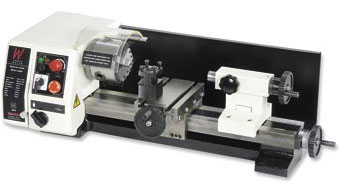
When we purchased the milling machine which was later converted to be CNC we also purchased an Axminster SIEG C1 Micro Lathe, the lathe was ok for working with larger materials (over 3mm) but due to excessive vibration from the machine when it was running it wasn't possible to work smaller materials and get a consistent finish.
Recently we needed to make some small parts on the lathe and found that it wasn't possible so we decided to see if we can improve it!
Removal of the covers and replacement of various parts narrowed the source of the vibration to the standard pulleys which had over .5mm offset which caused a lot of issues and the motor mount which flexed a lot when under load.
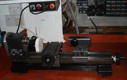
The original machine before starting work.
The first job was to relocate the electronics and speed controller to allow us to run the lathe with the covers removed. The control board was fitted into a plastic box and was fitted to a shelf above the lathe.
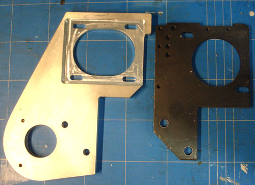
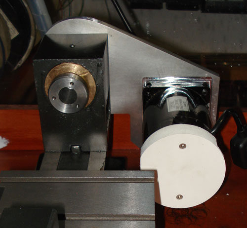
The original cogs, pulleys and motor mounting plate were removed and then scanned so a new mounting plate could be made using a 10mm aluminium plate.
View of the motor side of the new plate with original to the right.
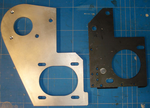
View of the pulley side of the new plate with the two new mounting holes in the top to fit into existing threaded M4 holes in the headstock.
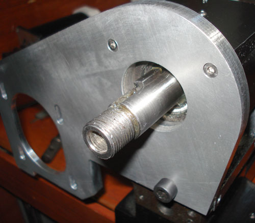
Close shot showing new mounting bolts recessed into the new plate.
The new pulleys were cut from a sheet of Delrin plastic initially using the milling machine to make the outline, the centres were then bored to the correct size and then the outside of the pulleys was machined on the lathe to make them round and a slot was created to work with the new V belt.
Testing the pulleys and belts.
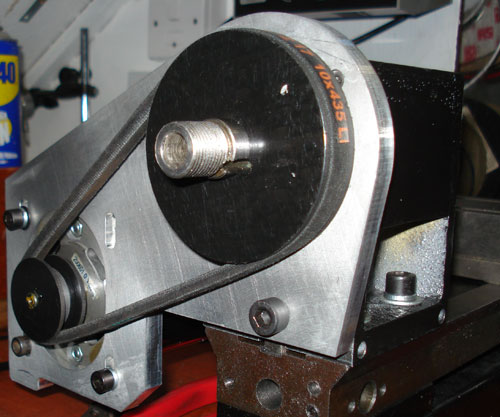
View of the motor mounted on the new plate.
The next stage is to make a second plate the same shape and fit this on spacers to cover the belt drive and then fit a cover over the top and an additional rubber foot below the motor.
The lathe is partially reassembled with the speed controller at the top of the photo.
The mill was purchased from Axminster tools and new materials from eBay and other metal suppliers.
Rodrigo
Hi!! I’ve come across your modifications on your mini lathe C1. What else did you do?
I own one of these and I’ve converted it to CNC. I need to align the headstock slightly with the ways.
Is there an easy way to do it? Do I need to remove the plastic cover, electronics all to be able to find the screws under the spindle case? Did you need to align the headstock of yours?
Thanks!!
Banjo
Could you post a specification/size of the pulleys made and the v-belt used in this mod.
Thanks
Brian
Banjo, I am sorry but I can not find the specs of the pulleys from the order.
Banjo
Did you made those pulleys similar in size to the original or did you adjust them to fit the new v belt?
Brian
Banjo, I made the metal plate to fit the new pulleys and v belt.