Following from the Automatic component feeders DIY pick and place Part 1 post we have now redesigned the Y axis which pushes the activation arms on the Panasonic component feeders to use a new leadscrew from Reliance Precision Mechatronics (part number LBF5-0375-150MM) which has a 9.53mm lead and 5mm diameter. This gives us a much faster and smoother activation rate on the component activator.
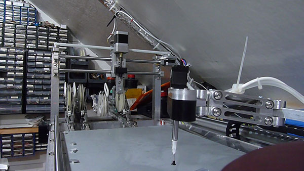
The mechanical microswitches we had fitted as limit switches were not very reliable and didn’t always stop in the same location due to the flexibility of the switch arms. To solve this problem we changed the switches for optical break beam sensors which are connected to the Arduino board and this gives us a much more reliable method of detecting the end stops of each axis on the component selector system.
The Arduino has been programmed to read the serial console input and by entering a number between 0 and 9 and certain letters such as (r) for reset and (u) for up the feeder will move to the correct component feeder and move the Y axis arm down to feed the component and open the access area on the feeder. When the next component is selected the Y axis moves back up and the feeder repeats the process.
Now the hardware side is working we need to fine-tune the location array which holds the component feeder locations on the X-axis and then write a control app to communicate with the Arduino via UART. I am planning to use an IOIO board with an Android tablet to make an interactive component picker which can run scripts to supply the correct components in sequence to build our PCB boards.
Once all the code is working, I will add it to the blog.
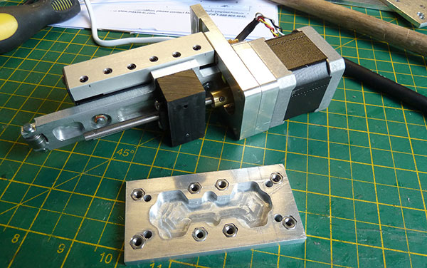
The photo below shows the Y-axis activator with lead screw and NEMA 17 stepper motor. The plate with the nuts embedded fits between the bearing blocks and the vertical slide rail assembly.
Comments