Today we finished the machining and building of the first of two solder feeders for our DIY soldering robot project.
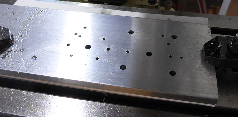
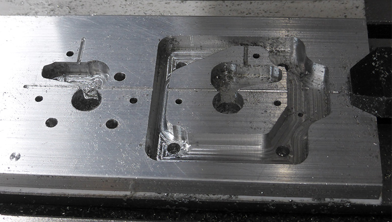
The main body of the feeder was milled from 10mm aluminium and the tensioner roller assembly was milled from 6mm aluminium sheet. The entire milling and machining process took about 6 hours overall including work on the lathe to make smaller parts and pivots.

The solder feeder works in a similar way to the filament feeders on 3D printers with a stepper motor with a small pinion cog and a sprung roller which provides tension between the solder and the gear teeth.
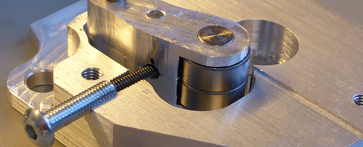
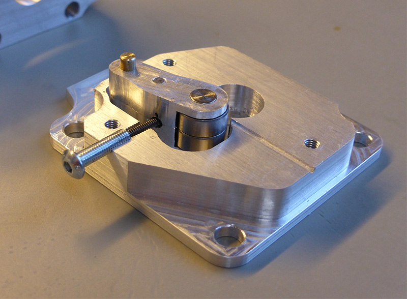
We used a small 1.5mm diameter spring which was fitted partly into an M3 12mm bolt which was centre drilled using a 1.7mm drill to allow the spring to go inside the bolt. This is screwed into the top of the assembly to provide a sprung force against the tensioner roller assembly.
Loading the solder is simply a case of pushing the solder into the entrance when the stepper motor is running, it automatically feeds through the drive gear and out of the hole on the far side. We added a piece of 2mm brass rod to the exit side so that we can easily attach a flexible pipe that will connect the feeder system to the solder head assembly.
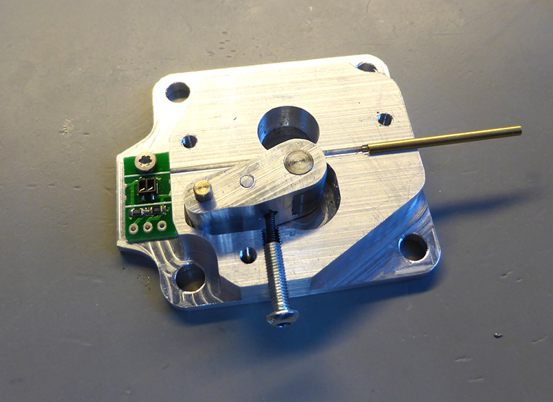
An optical sensor fitted to one side of the feeder will give us the ability to detect when the solder roll has run out and automatically pause the soldering program so we can load a new solder reel.
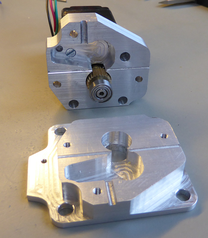
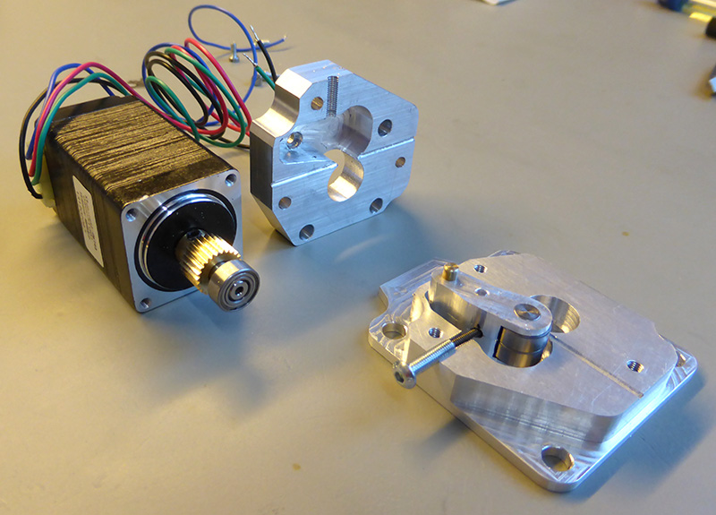
The stepper motor is a NEMA 11 high torque model from zappautomation and the drive gear is a brass gear with a 5mm shaft from eBay. www.ebay.co.uk
We have uploaded a PDF file and Cambam CNC file for the parts to https://github.com/briandorey/Soldering-Robot-Project/tree/master/
A trial version of Cambam studio can be downloaded from www.cambam.info
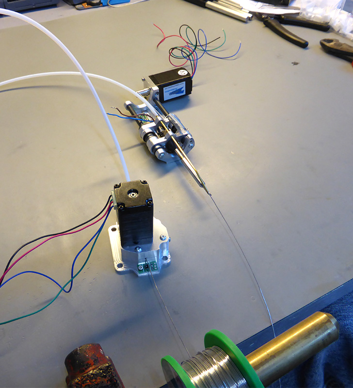
The video below shows the first test run with the stepper being driven using an Arduino Uno and stepper driver to move forward a preset distance.
Comments