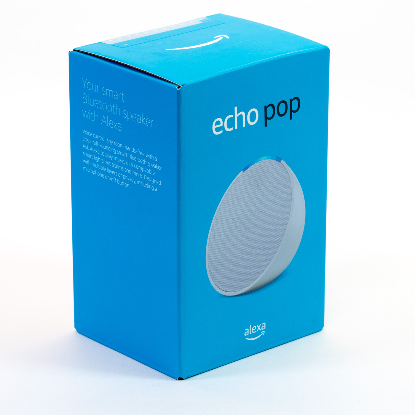
In this teardown, we will look at the new Amazon Echo Pop which is the latest Amazon Echo smart device from Amazon and was sold from the 31st May 2023 in the UK and currently costs £44.99 from Amazon UK.
We have previously torn down Amazon Echo devices, including the 3rd gen Dot, 3rd gen Dot with Clock, the Flex, the Echo Input, Echo Dot 4th Generation and the Echo 5th Generation.
The new Echo Pop comes in four colours, Charcoal, Glacier White, Lavender Bloom and Midnight Teal.
We purchased the Glacier White version on Amazon Prime Day when the device was sold for only £17.99.
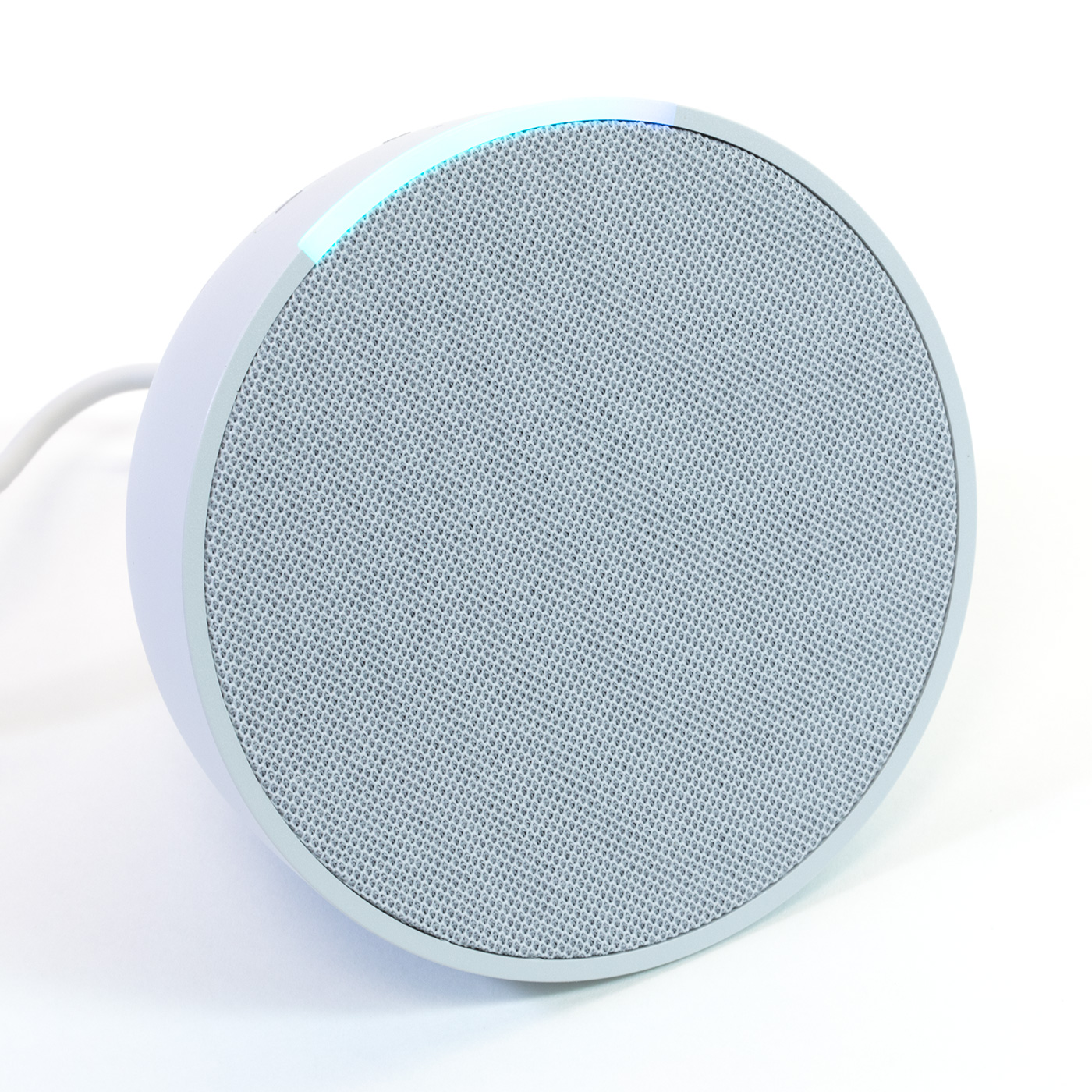
The Echo Pop is a semi-circular smart speaker measuring 99 x 83 x 91 mm with three buttons on the top for Mute, Volume Up and Volume Down.
The power input socket is on the rear of the device, and the base has a circular rubber pad to stop it from moving around on flat surfaces.
The device supports Wi-Fi, Bluetooth Low Energy Mesh, and Matter controller.
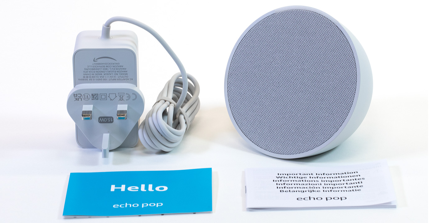
In the Box
- The Echo Pop
- 240V UK power supply
- Setup instructions
- Terms of use
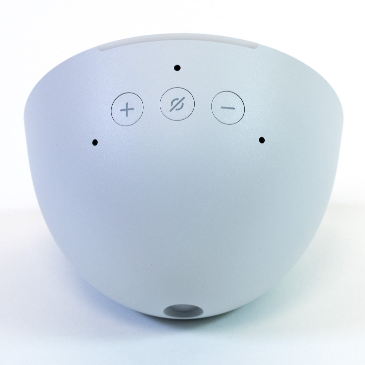
Top of the Echo Pop
The top of the smart speaker has three buttons. The + and – buttons control the volume, and a circle with a line through it which disables the microphones.
There are three small holes which are used by the internal microphones.
On the front edge of the case is a LED indicator plastic bar, this displays different colours depending on the task being performed and when changing the speaker volume the bar shows the current level running from left to right with the bar being fully illuminated when at maximum volume.
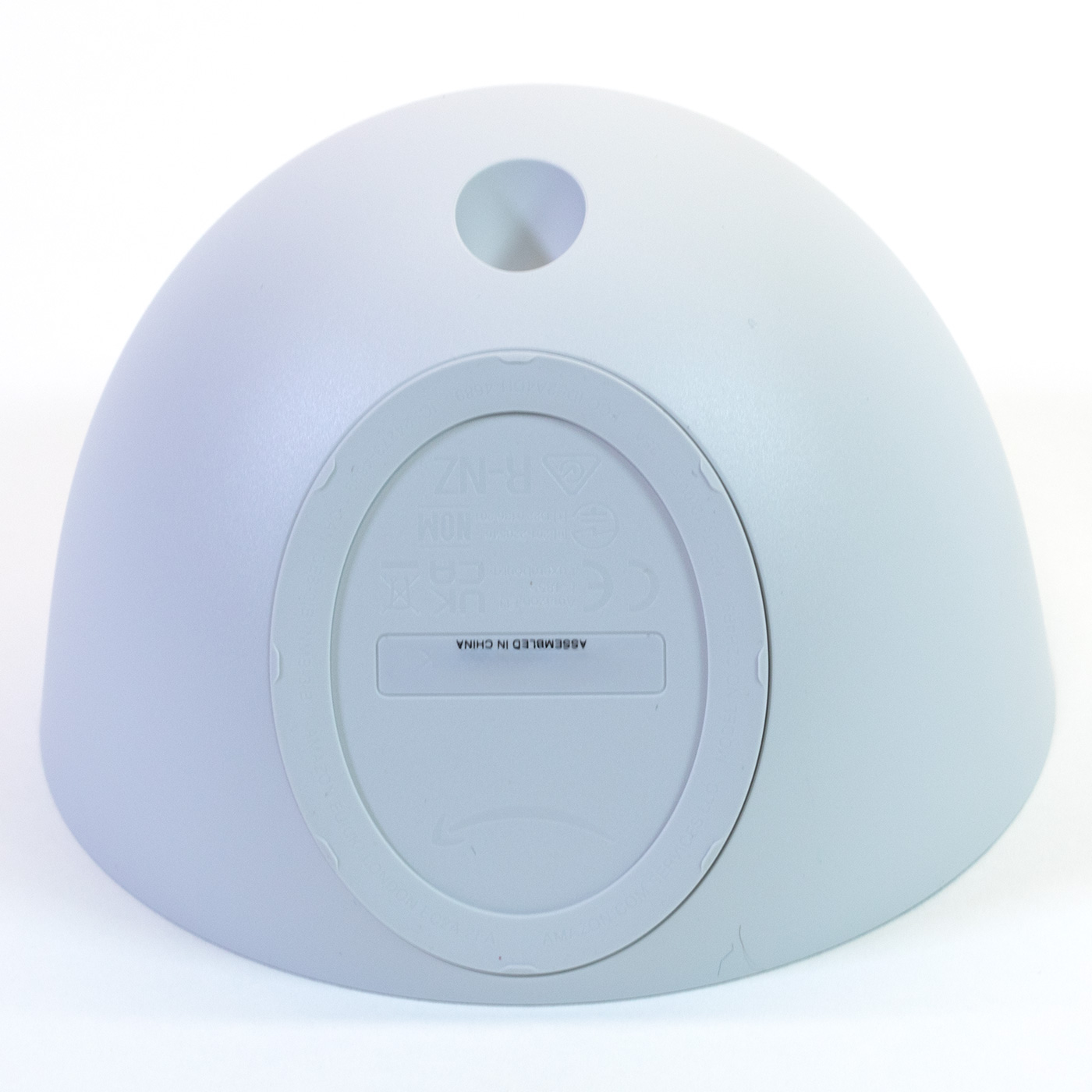
Case Base
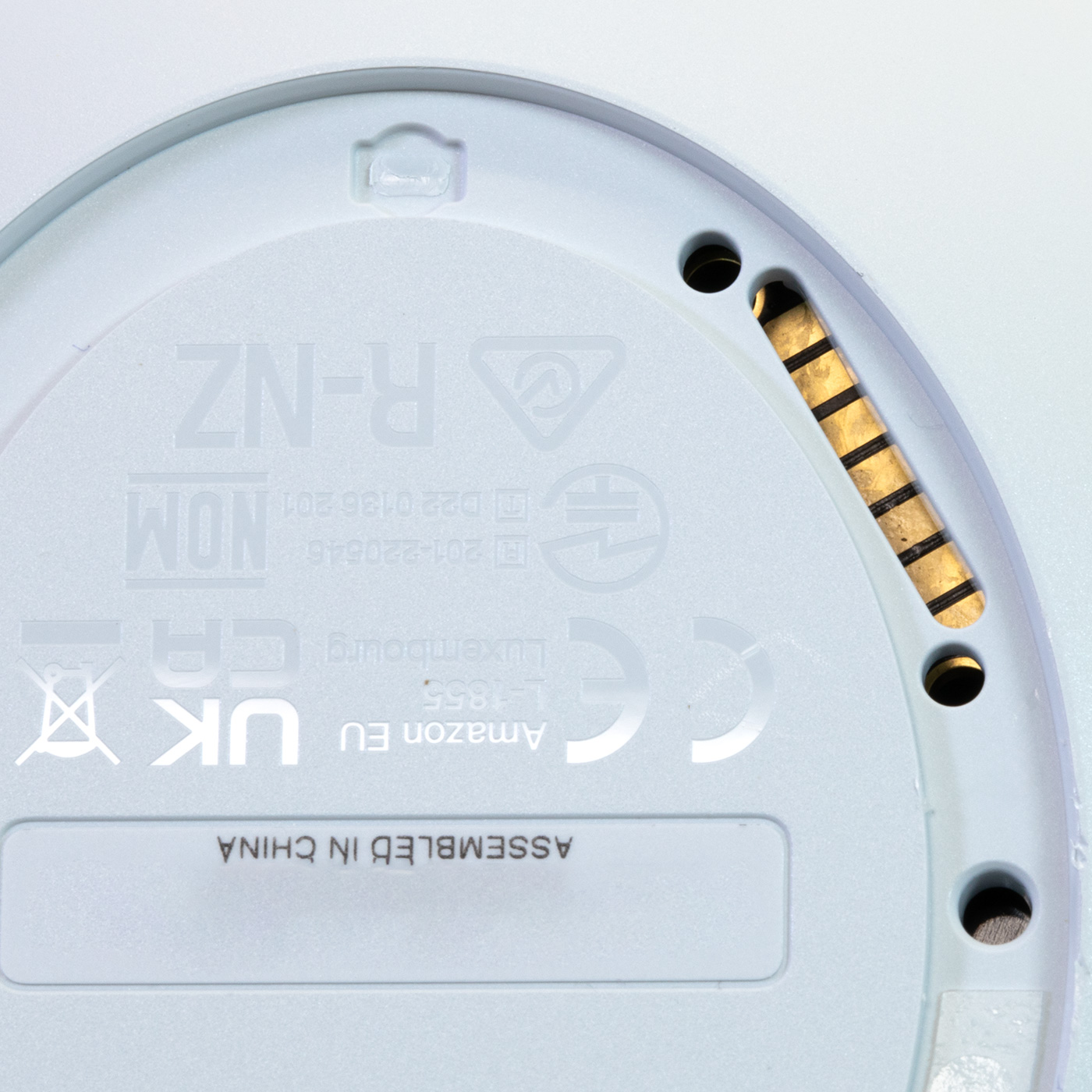
The base has the serial number, product logos, and certification marks.
On the rear is a power input socket. The Echo Pop does not have any external speaker inputs or outputs.
Removing the base rubber ring revealed an access hole with PCB pads which supply power and USB data for programming the device.
Unlike previous Amazon Echo devices we have torn down, the Echo Pop has no screws in the base, and access to the speaker and circuit boards is via the fabric-covered front panel.
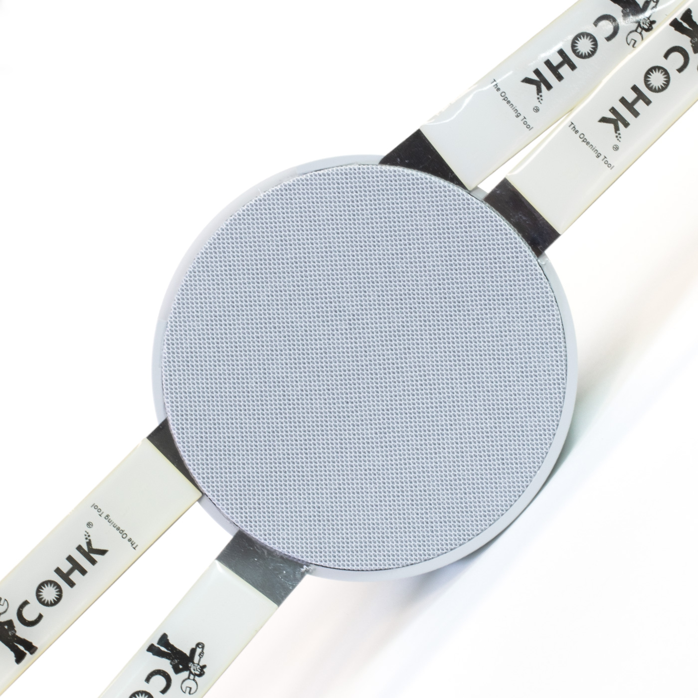
Opening the Case
Removing the front panel turned out to be much more challenging than expected. Using four metal spudger tools we carefully prised the fabric and plastic speaker cover away from the speaker enclosure to find that it was held in place using a very sticky double sized foam pad. This caused a small amount of damage in the outer plastic enclosure, but this should not be too visible when the Echo Pop is reassembled.
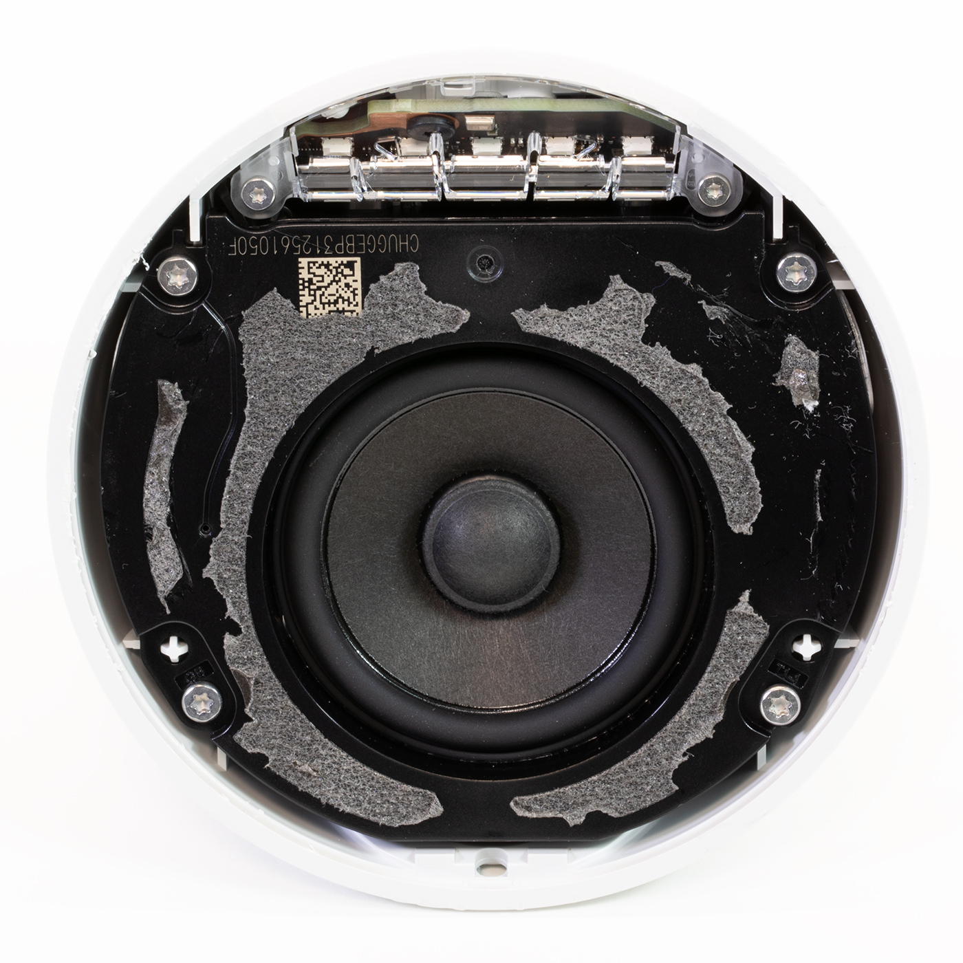
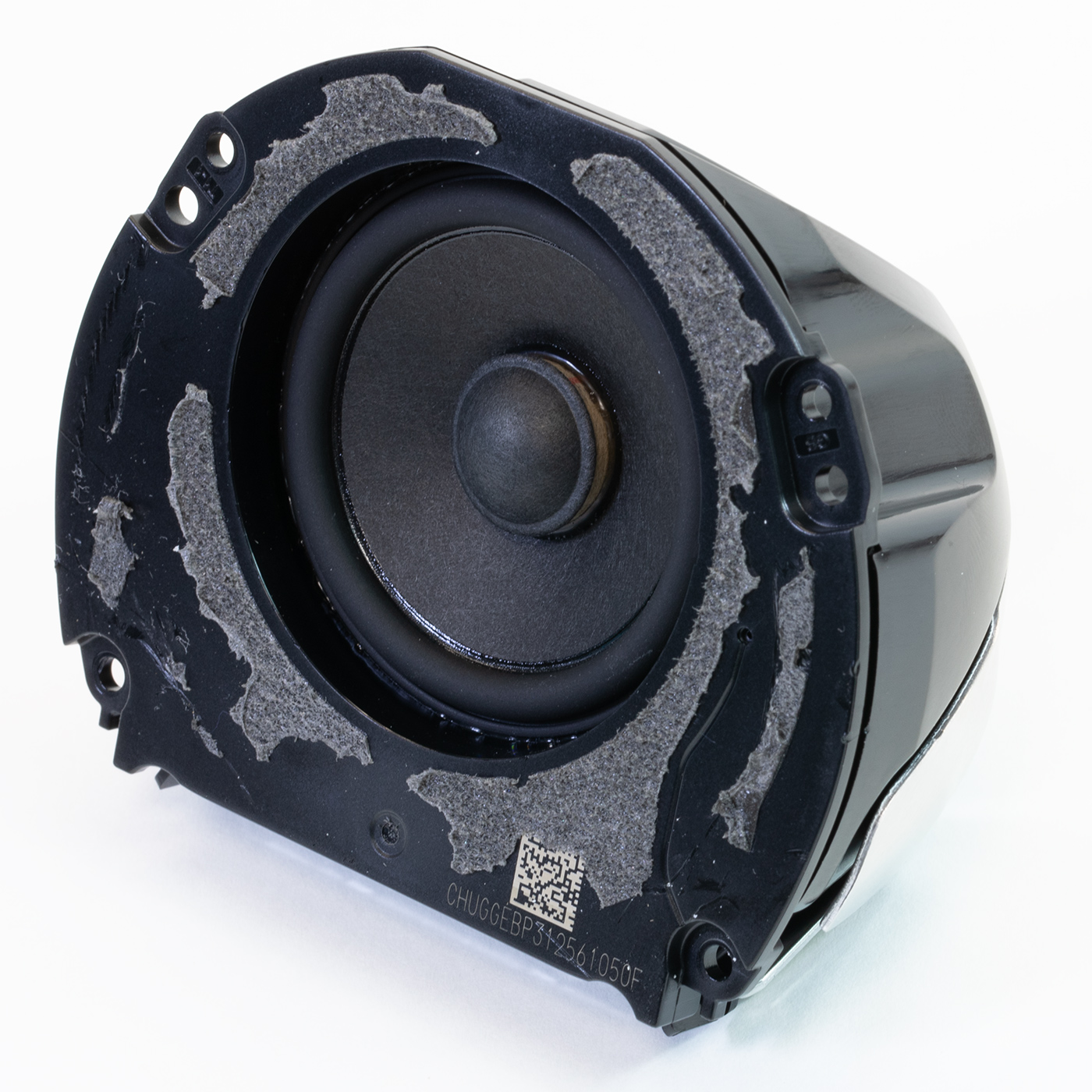
Speaker Enclosure and light pipe plastic
With the front cover removed, this reveals the internal speaker enclosure and a small clear plastic light pipe covered in black plastic tape.
This guides the light from the LEDs on the main PCB to the outer light indicator area at the top of the case providing a visual indication when the speaker is listening for commands or responding to inputs.
The speaker is held in place with four T8 torx screws, and the clear plastic light-pipe panel has two T6 torx screws holding it to the main case.
With these screws removed, the speaker and light pipe can be removed from the case.
The speaker enclosure is connected to the PCB using small metal tabs that touch pads on the PCB to drive the speaker.
The single internal speaker measures 49.5mm and is inside a sealed black plastic enclosure with an aluminium heatsink around the sides to dissipate heat from the processor.
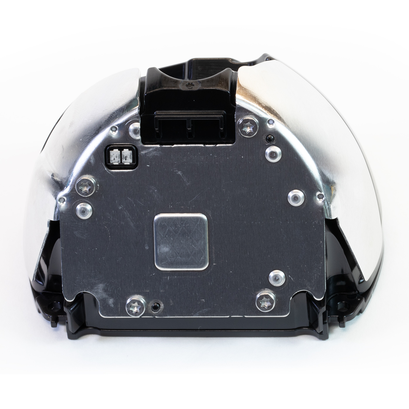
Main Processor PCB and Power / Debug PCB
With the speaker and light pipe removed this reveals the main PCB and a small secondary PCB with the power socket and a USB debug header connected by a short cable.
The power input PCB is secured using two T8 torx screws, and the main PCB has three small black T6 torx screws securing it to the main case. The PCB is also clipped into the top of the case and must be carefully lifted from the buttons.
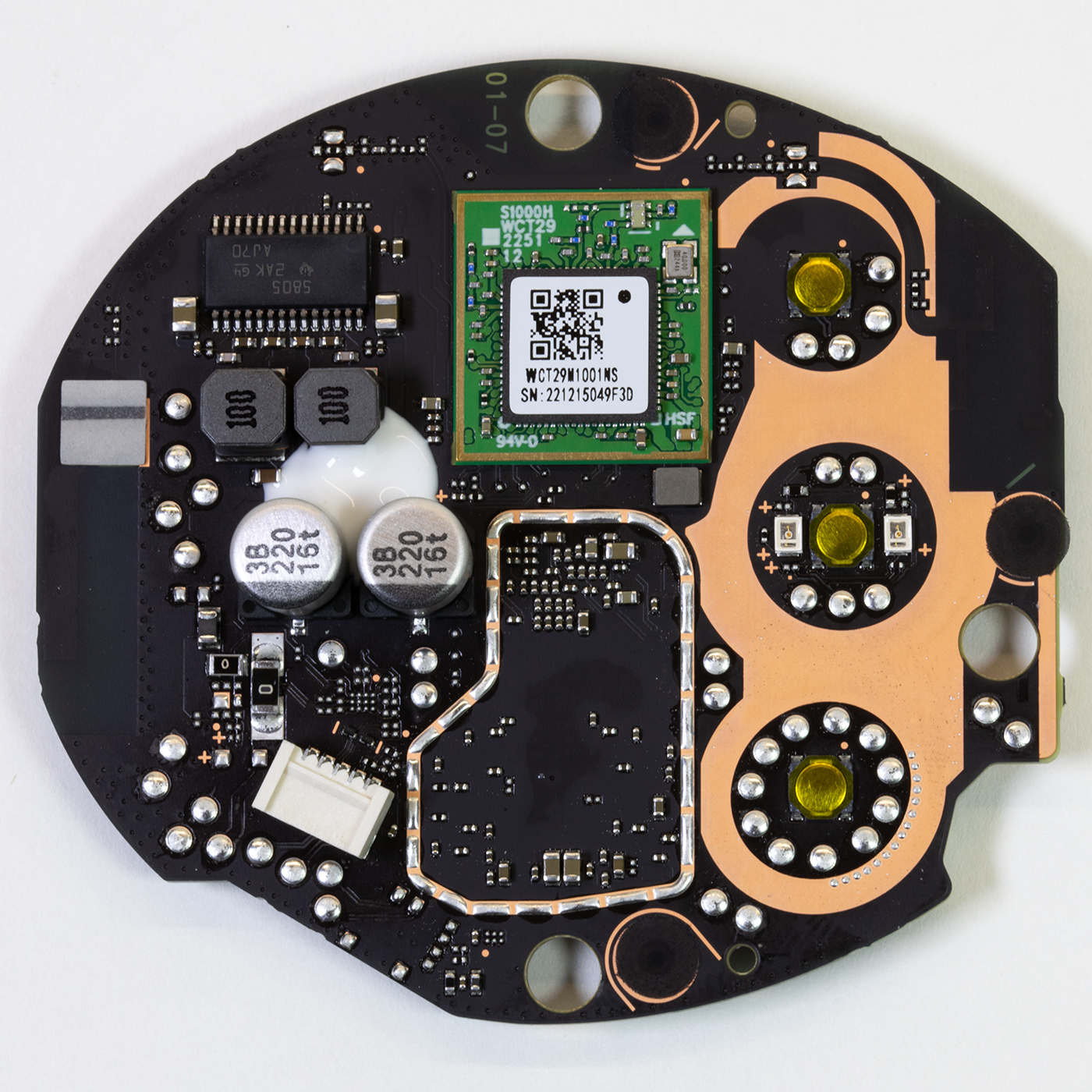
The upper side of the Processor PCB
The power / USB cable connector, power regulation, and a module on a green PCB marked S1000H WCT29 2251 12, and WCT29M1001NS are on the top of the main PCB.
Removing the sticker on the chip reveals the part number MT7653BSN, an 802.11ac Wi-Fi and Bluetooth 4.0 controller. This is the same wireless chip on the main PCB on previous Echo devices but has now been moved to a daughterboard.
There are three control buttons and holes for three microphones.
Audio for the speaker is provided by a Texas Instruments TAS5805M 23-W stereo, 45-W mono, 4.5- to 26.4-V supply, digital input Class-D audio amplifier with enhanced processing.
The lower side of the PCB
A large metal RF shield with a thermal heat transfer pad in the centre dominates the lower side of the PCB. The PCB is marked with a version number: SH14 94V-0 E248779 and a date code of 0423.
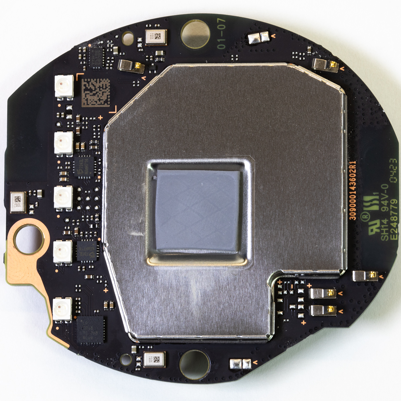
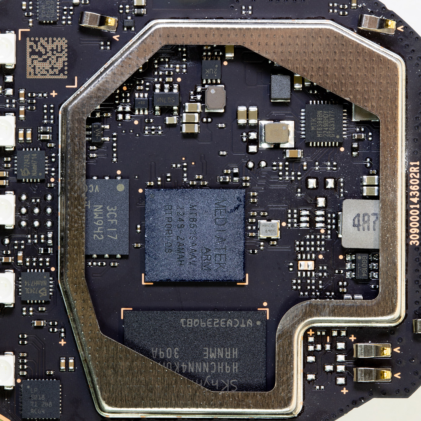
Removing the metal shield, which is not soldered to the board in this version, reveals the processor, memory, and other chips.
Chip locations are referenced to the image below.
Starting on the top-right of the metal shield area is a chip marked MTK MT6398BN, which is an unknown MediaTek part used on other Amazon Echo devices, based on the surrounding components, it appears to be a switching power supply.
In the centre of the board is the MediaTek Arm Processor MT8519AAAV. I have not found any information online for this part number.
To the processor's left is the RAM module marked SK HYNIX H9HCNNN4KUMLHRNME.
Below the processor is the NAND flash memory made by Micron, part number: 3CF17 NW942
Along the upper left side of this photograph is a chip marked 46095 3B110MAA, which I have not been able to identify.
Next to the four LEDS on the left side, are two chips marked: 7243L NAmH714, possibly LED drivers.
To the left side is a chip marked: LP 5078 TI 2B8 AC64, which is also an unknown part.
The Echo Pop uses three microphones placed on above and below the processor area and one on the left edge.
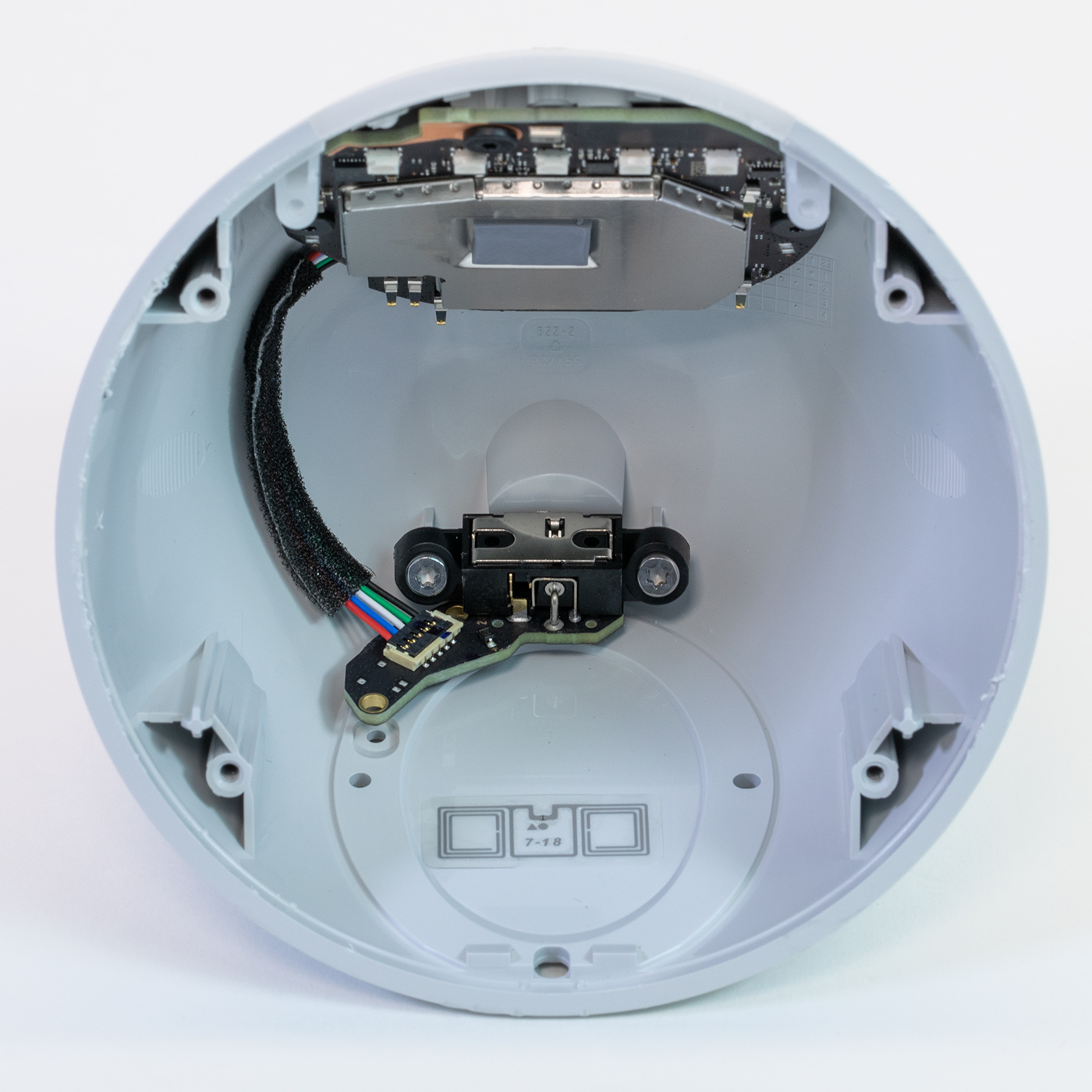
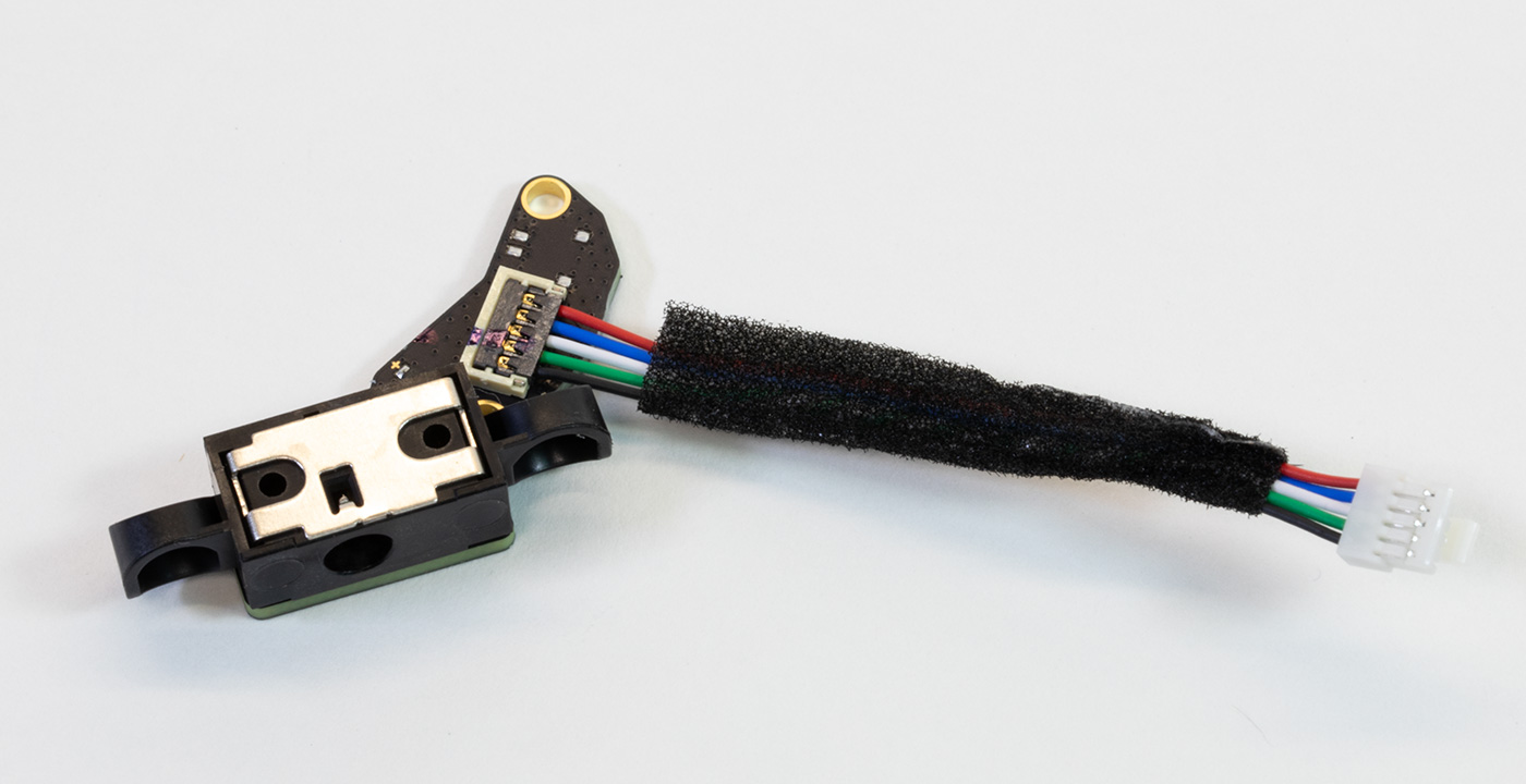
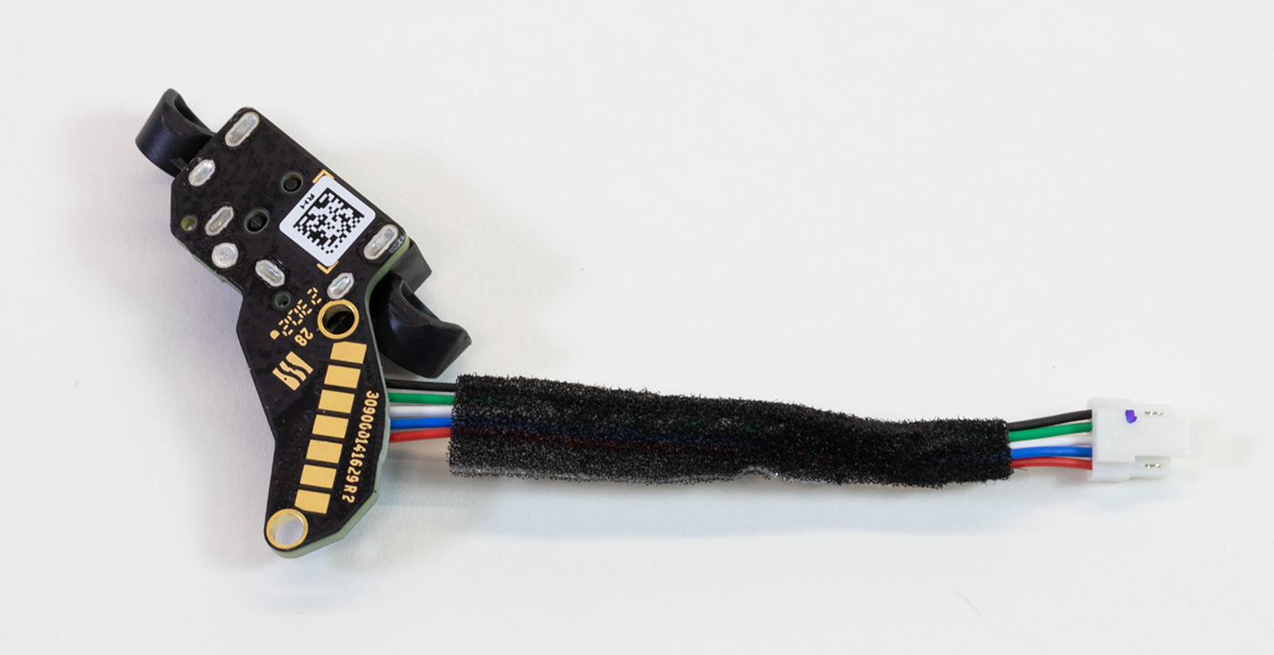
Power input and Debug header board
At the rear of the Echo Pop enclosure is a small power input PCB which connects to the processor PCB using a small cable.
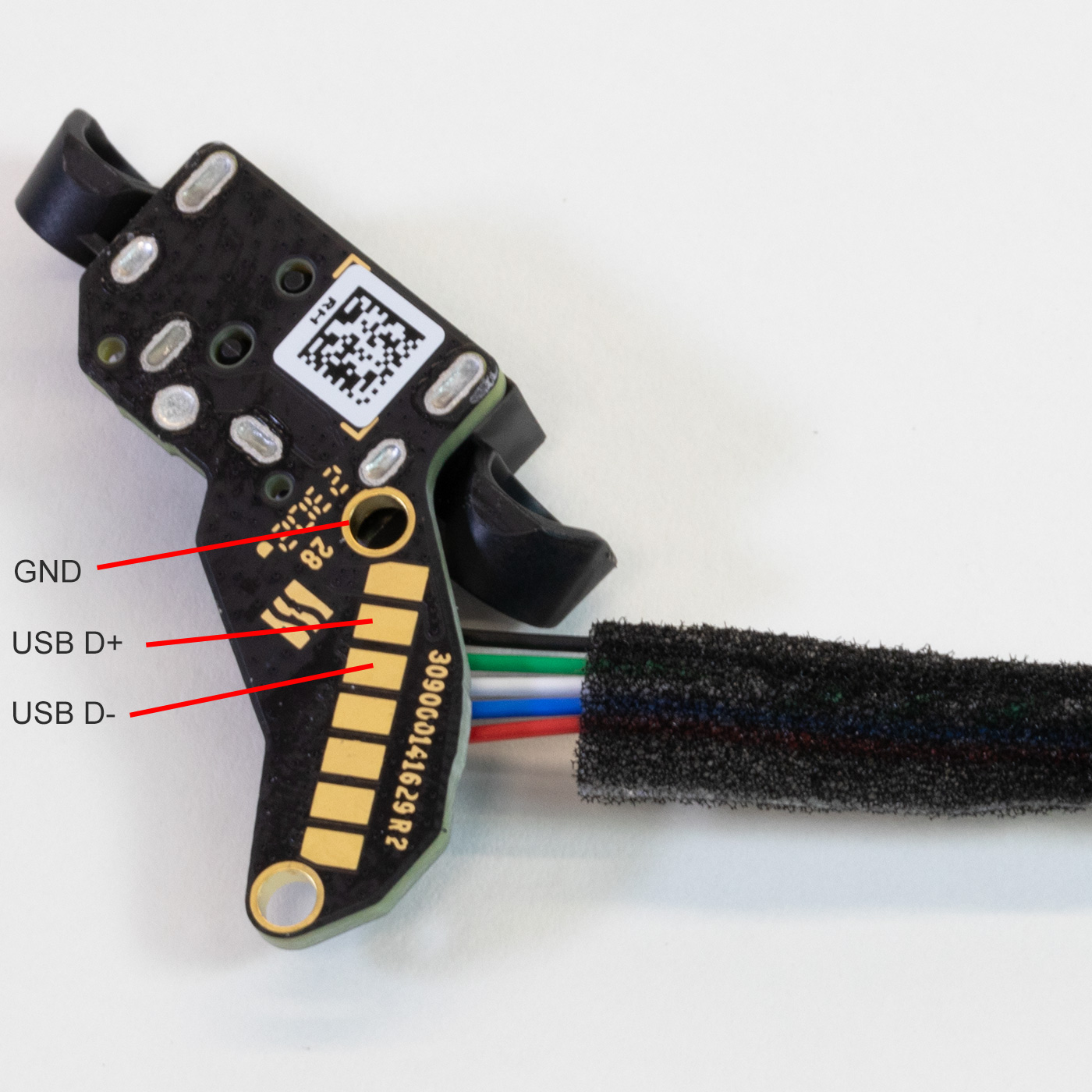
On this board is a row of seven exposed pads with locator holes. These pads are visible when the Echo Pop is assembled under the base rubber ring.
After checking the connections to these pads we found that the following connections are available:
Ground (GND) on each location hole connected to the black wire.
USB D+ connected to the green wire.
USB D- connected to the white wire.
Connection to the blue wire, which we are unsure of its purpose.
Connecting USB to the computer
We used a spare USB cable to solder connections to the GND, D+ and D- pins and after connecting this to the computer, we could enter the bootloader mode by holding the volume down button and then connecting the power.
After a few seconds, the computer would recognise the device, and the LEDS would all turn green to indicate it was connected to a host computer.
Using a Linux virtual machine with Android development software installed, we tried to query the chip using the fastboot command, but we found that it only supports a limited set of available variables as it is using version 0.4.
The full fastboot specification is available to view at u-boot.readthedocs.io/en/latest/android/fastboot-protocol.html
The data we have been able to receive was:
| Variable | Data |
|---|---|
| version | 0.4 |
| product | churro |
| version-bootloader | U-Boot 2019.04-g566fab8 |
| version-baseband | N/A |
| secure | Yes |
| serialno | Not shown on this post but matched the serial number on the box. |
As we have not been able to obtain further details using the fastboot software, we are unsure if it is possible to flash other firmware onto the chip. As its secure status is locked, it would need to be unlocked before any changes could be made.
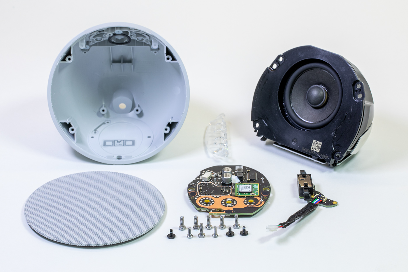
All internal parts
All the internal parts that make up the echo Pop.
Power Consumption
We measured the peak power consumption of the Amazon Echo Pop with a Hopi mains power meter.
| Device Status | Power in Watts |
|---|---|
| Booting the device | 2.1W |
| Idle waiting for input | 1.1W |
| Responding to a user command | 1.8W |
| Medium volume with music playing | 4.1W |
| Maximum volume with music playing | 6.3W |
Comments