
This is the third and final part of a three-part series on designing and building a barcode scanner using a Raspberry Pi Zero W.
Raspberry Pi Zero Handheld Barcode Scanner Part 1
Raspberry Pi Zero Handheld Barcode Scanner Part 2
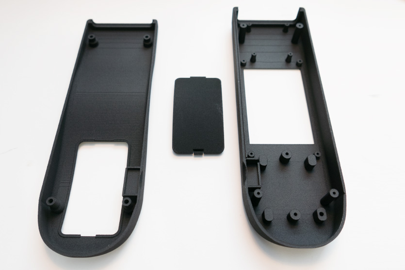
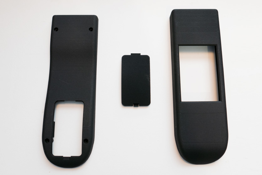
In the previous blog post, the circuits were finished and a case was designed and sent for printing with Shapeways. The case arrived within a couple of weeks and overall, I found the service from Shapeways to be excellent. They sent us an email a few days after ordering saying that the case had banding lines along the surfaces and asked if we still wanted it. The design had several surfaces with very shallow curves and as 3d printers work by laying down thin layers of plastic on top of each other banding on the surfaces was to be expected so we told them that it would be fine and they shipped the case to us.
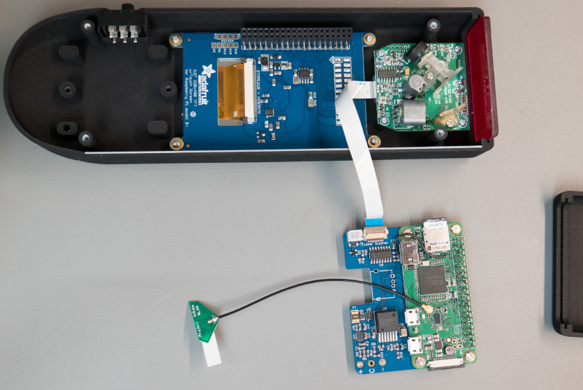
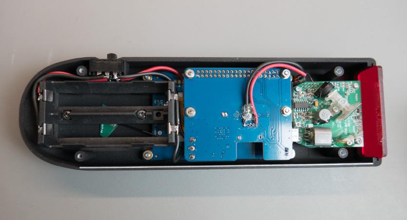
When the case arrived, we found a couple of small problems with our CAD design. One half of the case had a flange around the edge that was supposed to sit inside the other half when they are put together to keep the edges aligned. On one side of the case the flange lined up perfectly but I made a mistake with the alignment of the flange on the other side it was about 0.5mm out so the case would not close tightly together. A sharp knife solved this problem. The second problem was with the battery cover. I made the tolerances between the case and the battery cover too close and they would not clip together properly but a rub around the edges with a bit of sandpaper solved that issue. Other than those problems everything worked fine. The internal mounting holes all aligned with the PCBs and the LCD display lined up with the hole in the top.
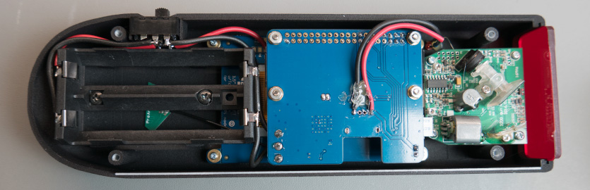
We used a piece of 3mm red transparent acrylic for the front of the case where the laser shines through. Once everything was assembled, we found that where we had put the laser PCB flat inside the case some of the laser beams were reflecting back off of the acrylic into the sensor stopping it from reading barcodes so we put some spacers between the case and the front of the scanner PCB to offset the angle. This meant that the laser now pointed downwards slightly and any internal reflections off of the acrylic would not be bounced back into the sensor allowing it to work correctly. After we found this issue I went back to look at the case the scanner assembly was removed from and found that the red acrylic cover on that was offset from 90°. If I had noticed that before designing the case I would have made the front mounting posts for the PCB longer.
We added a red LED to the top of the case connected to the 5V pin on the Raspberry Pi. This was needed because when the Raspberry Pi is shut down it turns off the backlight on the LCD so there was no way of seeing that the barcode scanner was still switched on other than looking at the direction of the slide switch on the side. As it would be easy to accidentally leave the device switched on it was decided that an LED on top would make it easier to see if it was still powered.
With the case assembled the next stage was to design the software to run on the barcode scanner. The original plan was to use apache and run a web application on the Raspberry Pi with a web browser displaying everything on the LCD. We got quite a way into building the project this way before finding that the performance of the Raspberry Pi Zero was too slow to make a usable user interface. The refresh rate of the browser when scrolling was less than 1 frame a second so if you tried to scroll up through a list of orders you would swipe your finger upwards and a couple of seconds later the screen would update to show that you had scrolled too far. As this would be unusable for a device that would be in regular use we decided to scrap the web application idea and build a normal GUI application to run on the Raspberry Pi.
An application designed in assembly language or C would have given the best performance on the Raspberry Pi but as I don’t have any experience designing GUI applications in C and the only assembly language programming I have done is flashing an LED on a PIC microcontroller it was decided that a python program using TkInter for the GUI would be a better approach. Slower in performance than a compiled C program but quicker than a web application.
The first job was to create a flow chart of how the software would work. (click to view PDF)
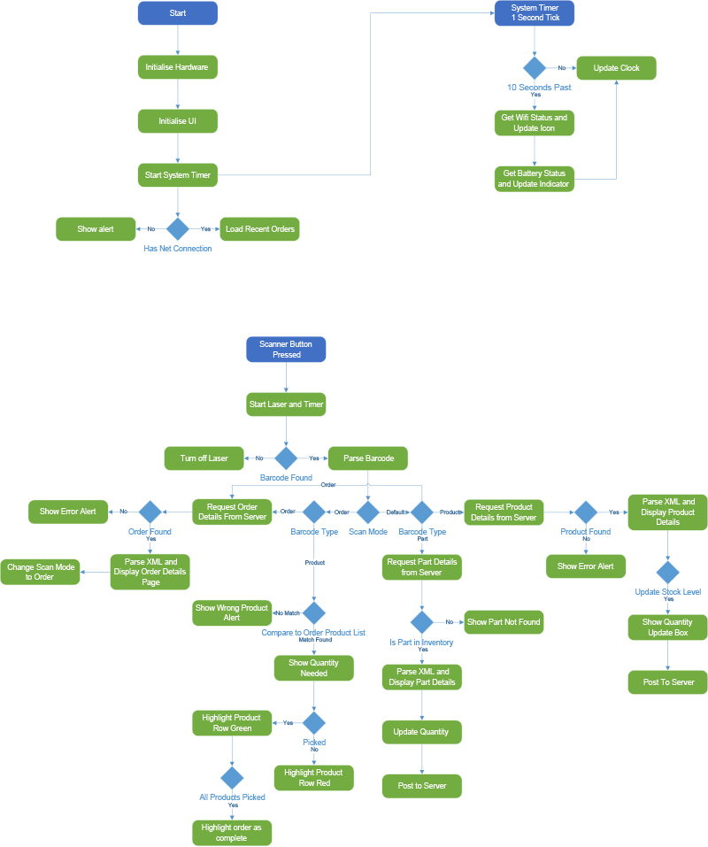
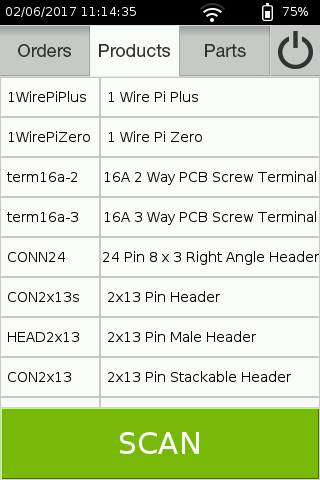
The software is designed to integrate into our e-commerce and inventory manager and has three main sections, orders, products and parts. A tab bar at the top of the screen allows you to select which section you want but when you scan a barcode it will automatically detect the type and put you into the correct section of the application.
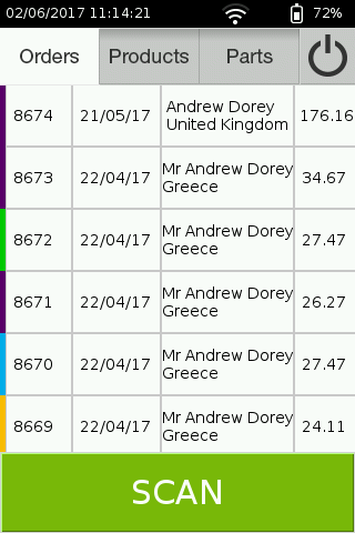
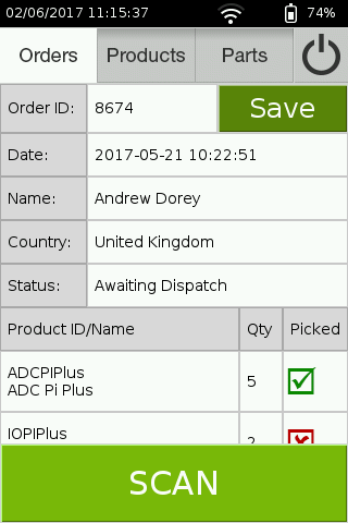
The orders section displays a list of outstanding orders on our e-commerce website. Each invoice we print has a barcode on it that contains the order number so scanning the barcode tells the application which invoice it needs to retrieve from the server. Once the order details are received it displays the details for the order with a list of the products that have been bought. Each product is then scanned as it is picked for the order and the application updates to show if the correct number of items have been picked. For items that do not have a barcode like connectors, you can manually enter the number picked using a numeric keypad. Once the order is ready a save button sends data back to the server telling it that the order is processed and ready for dispatch.
The products section shows a list of the products for sale on the website. When a product barcode has been scanned the name and ID of that product are displayed along with any options that are available such as size or colour and the number of each option in stock. You can then add extra stock to the inventory or update the stock level manually. This section is designed so that when we build new stock we can easily add it to the website by scanning the barcode of the product and entering the number we have built.
The parts section still needs to be completed but this section is designed to integrate with the internal intranet that we use to keep track of the components used when building our products. When a new roll of resistors or chips arrives, we will be able to scan its barcode and enter that number into the inventory. The intranet is still under development but the plan is to make a system integrated with the barcode scanner and our pick and place machine so the scanner adds stock to the system and the pick and place machine automatically deducts parts from the stock every time it picks a part to go on a product. That way we will always know how many of every component we have in stock and forecast when we need to order more.
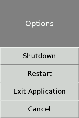
A title bar was added along the top of the screen which shows the current time, Wi-Fi status and battery status. The battery status is based on the voltage of the lithium cells which we profiled to get the correct voltage curve. A power button was added on the tab bar which brings up a screen where you can shut down or restart the device or exit the application which returns you to the bash shell. Exiting the application should only be needed during development and debugging. If the application does crash then it is possible to SSH into the barcode scanner over the Wi-Fi connection to find out what went wrong.
The TkInter GUI python library does not include support for touch screens so we had to write our own methods for detecting touches and drag events. This was done by detecting the position of the cursor on press and comparing its position and the time to release. If the position was close and the time was less than 1 second then it was detected as a click. If the cursor moved between the press and release then that was detected as a drag event and the content frame was moved to match the distance the cursor moved. A timer was started on the press event and the position was checked and updated every 10ms. This resulted in smooth scrolling when you press and drag your finger across the screen.
With the software ready, the barcode scanner was complete. Initial tests show that we should get around 10 hours of battery life out of a pair of 18650 lithium battery cells. As the scanner will probably only be needed for around half an hour each day when we are packaging orders we should only need to recharge it twice a month.
The hardware design files and software for this project can be found on our GitHub repository.
The internal WiFi antenna we used for this project was from https://uk.rs-online.com/web/p/wifi-antennas/7043326/


Michael Vieweg
Hi Brian. Would it be possible to sell your PCBA for this scanner project on your shop?
I'm interested in this project and would like to build one scanner for myself.
Brian
Hi Michael, You can downloads the pcb files from the GitHub link above and https://www.elecrow.com/pcb-manufacturing.html will make the boards for you.
Zak
Could you point me in the right direction for the ribbon cable connector you used on the custom board? I'm having a hard time finding the right one.
Brian
The connector is a FH12-15S-0.5SH(55) made by Hirose Connector
https://www.mouser.co.uk/ProductDetail/Hirose-Connector/FH12-15S-05SH55?qs=Ux3WWAnHpjCekIvxd%252b1wfA==
Steve
I am wondering if by any chance you can help me with a question. Our company uses antiquated technology for capturing weights of product for export and the scan guns we are using are from the 80s and connect to an old dot matrix ribbon printer. Is there any way to use you Pi program to gather the data from these barcodes and store it in usable format for later printing from a newer printer.
Brian
Steve, it would be simpler to use a USB barcode scanner and a windows app or linux app to store the barcode data. The scanner modules output as a serial device so it would be fairly easy to save this data and then use it again to print on a new printer
Konrad
Great project! I've been following since the beginning. Thank you so much for making this available
Horst Meyer
This is a great project and I would love to replicate it. Unfortunately the template is too big for my 3D printer. Would it be possible to disassemble the two large parts again, because I can not print them with my 3D printer, because they are still too big. You could provide the parts with tabs that you can then screw. Scaling makes no sense, because the boards no longer fit in there. Unfortunately I don't know CAD very well. Thank you very much.
Brian
Hi, I am sorry but we do not have access to the 3D software we used to create the models and so we cannot edit them to make the parts smaller.