
This is the second part of an ongoing project to build a wireless barcode scanner based on the Raspberry Pi Zero. View part one here: Raspberry Pi Zero Handheld Barcode Scanner Part 1 and part three here: Raspberry Pi Zero Handheld Barcode Scanner Part 3
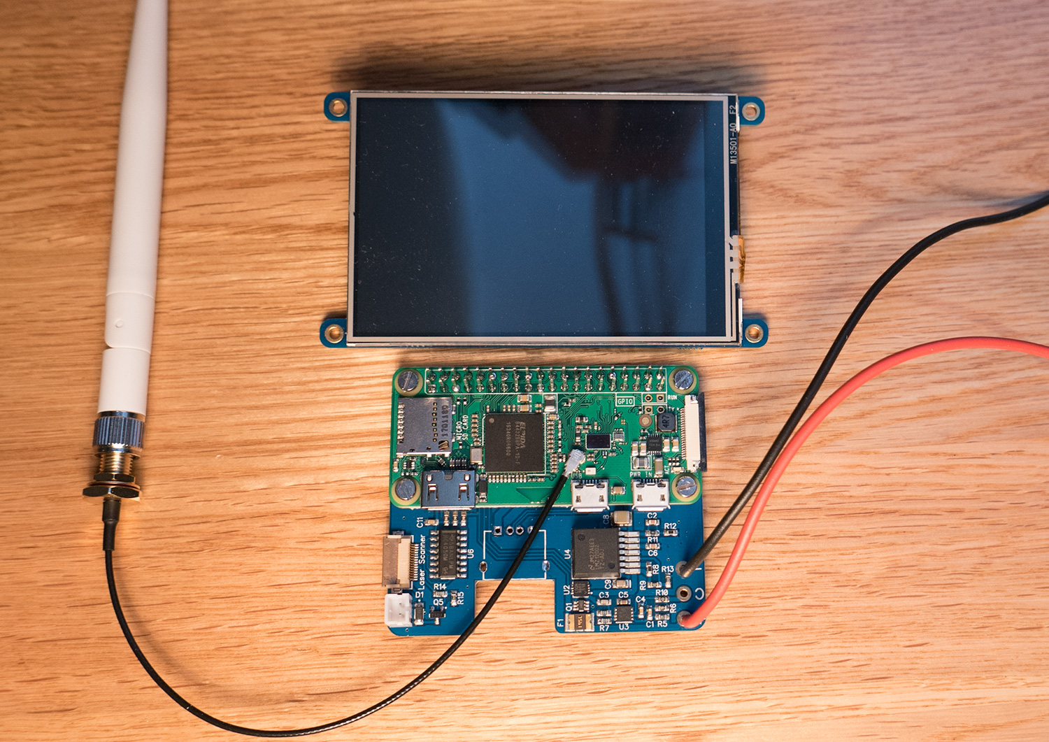
Since the last blog post, the PCB for the barcode scanner control board arrived and we assembled and cooked it in our reflow oven. The original idea was to use a Raspberry Pi Zero with an external USB Wi-Fi dongle fitted to the PCB on a right-angle USB connector but after building the control board the Raspberry Pi foundation released the Raspberry Pi Zero W which has onboard Wi-Fi.
We ordered a Raspberry Pi Zero W and when it arrived we noticed that there was space on the PCB to fit a connector for an external antenna. You can read about our attempts to fit an external antenna in the blog post Raspberry Pi Zero W external antenna mod. With the external antenna, socket fitted we tried connecting the Pi Zero W to the control board and found that using the onboard Wi-Fi instead of a USB dongle we saved about 100mA on the current consumption.
With the main control board complete we turned our attention to the display. We decided to use an Adafruit PiTFT 3.5 touch screen for the display and when it arrived we found that the 40-pin connector was a bit taller than it needed to be and there was a second set of pins for connecting to the GPIO port. After attacking the display with the hot air gun, we removed both of the connectors and replaced the 40-pin header with a lower-profile version. This combined with removing the plastic part of the GPIO pins on the Raspberry Pi meant that the overall height of the display and control board combined was just 20mm.
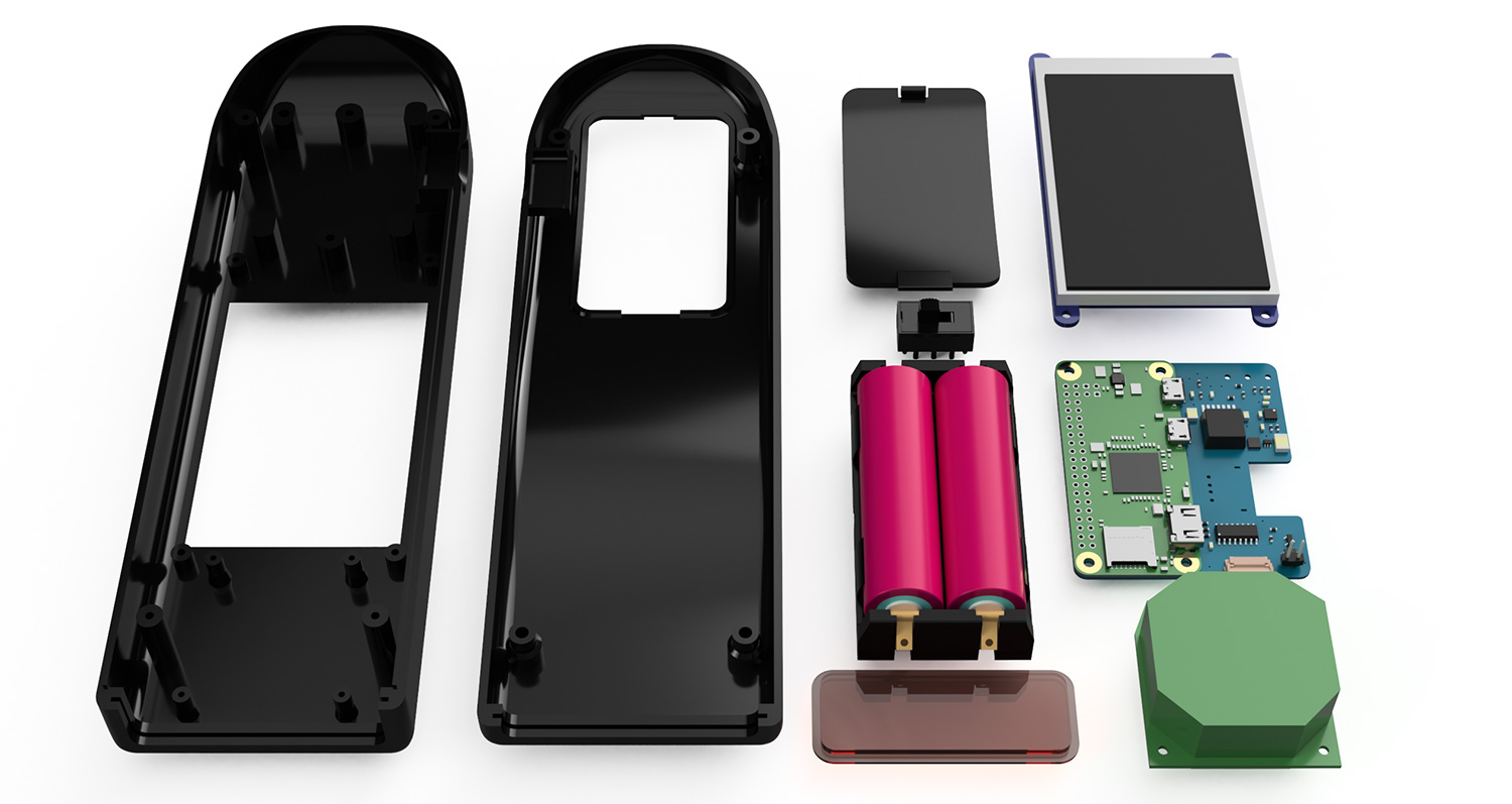
To power the barcode scanner, we are using a pair of 18650 lithium battery cells. Using external battery cells means that when the power gets low we can swap the batteries instead of waiting around for the scanner to recharge.
After finishing the circuit boards the next step was to design a case for the barcode scanner. We initially looked at machining a case out of Delrin or nylon but as we wanted something fairly large and complex we decided that we would try using one of the online 3d printing services that are available.
To design the enclosure, we needed to find a 3d modelling or CAD package. In the past, we have always used Adobe Illustrator for designing the cut files for our mill but as we needed to make a 3d object, Illustrator would not be suitable for the job. We initially looked at using Blender 3D for making the enclosure but after looking around at other available design packages we decided that Autodesk Fusion 360 would be better suited to the job. Fusion 360 is a cloud-based CAD and CAM package which runs a small application locally while most of the processing work is done on Autodesk’s servers. Autodesk has several useful tutorials on their website for beginners which was handy as this was the first time we had used a proper CAD package. After a few hours of watching videos and playing with the software, it was time to start designing the enclosure.
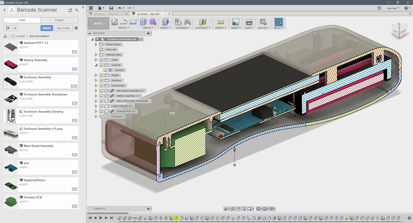
Fusion 360 software shows a cutaway of the new case with the boards and batteries inside
The first job was to export 3d models of the control board PCB in Diptrace and find or build models for all the other internal components. For the battery holder, we found a suitable part from Keystone Electronics, part number 1049. Keystone provides 3d models for their products on their website which is useful. We had to create models for the LCD display and the laser scanner module but we managed to find the models online for the switch and batteries.
With all the internal components ready the next step was to arrange everything and work out a basic shape for the enclosure. We started by drawing a curved spline around the outside of the components and then extruded it and filleted the edges to make the rough shape. After a bit of smoothing and adjusting, we had the design we wanted. The cut-outs were made for the LCD display, laser module and switch and internal mounting posts were added so we can screw everything down securely. For the battery compartment, a cut-out was made and a door was modelled based on the design found on the back of most TV remotes. Once we were happy with the overall design we split it into two parts, added a flange around the edge so it would slot together nicely and added four internal posts so the two halves could be screwed together.
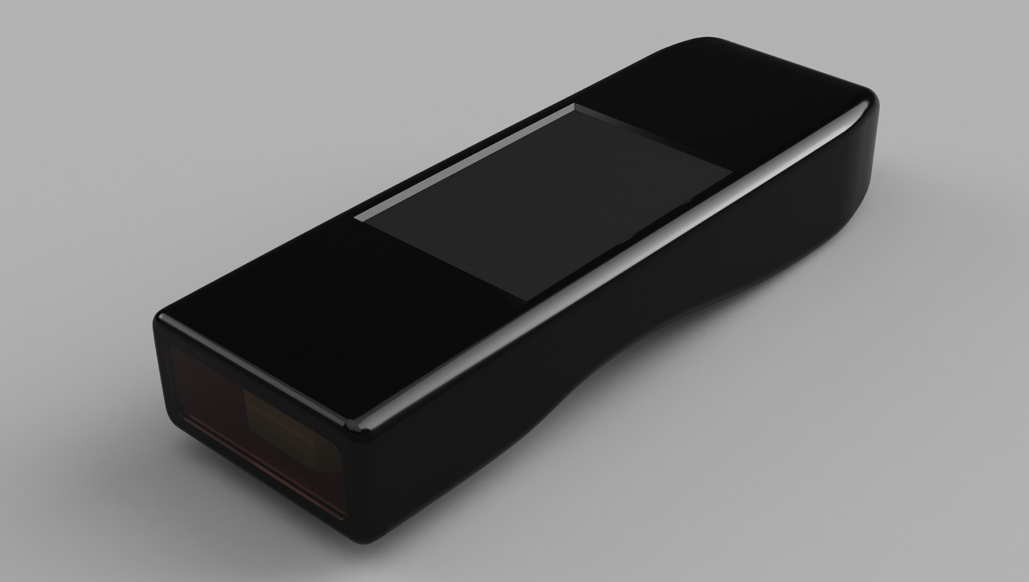
Once the enclosure was finished we tried rendering it with assorted colours to see how it would look. The clear Perspex finish looked best but as there would be lasers shining around the inside we decided that a clear box might not be the best idea so we went with a black finish to match the LCD display.
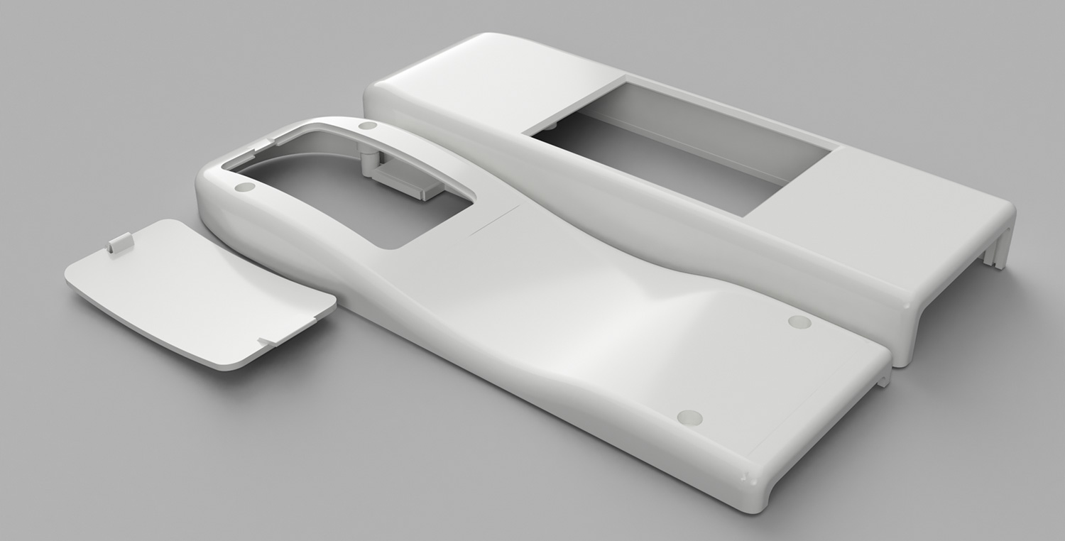
The case rendered using white material
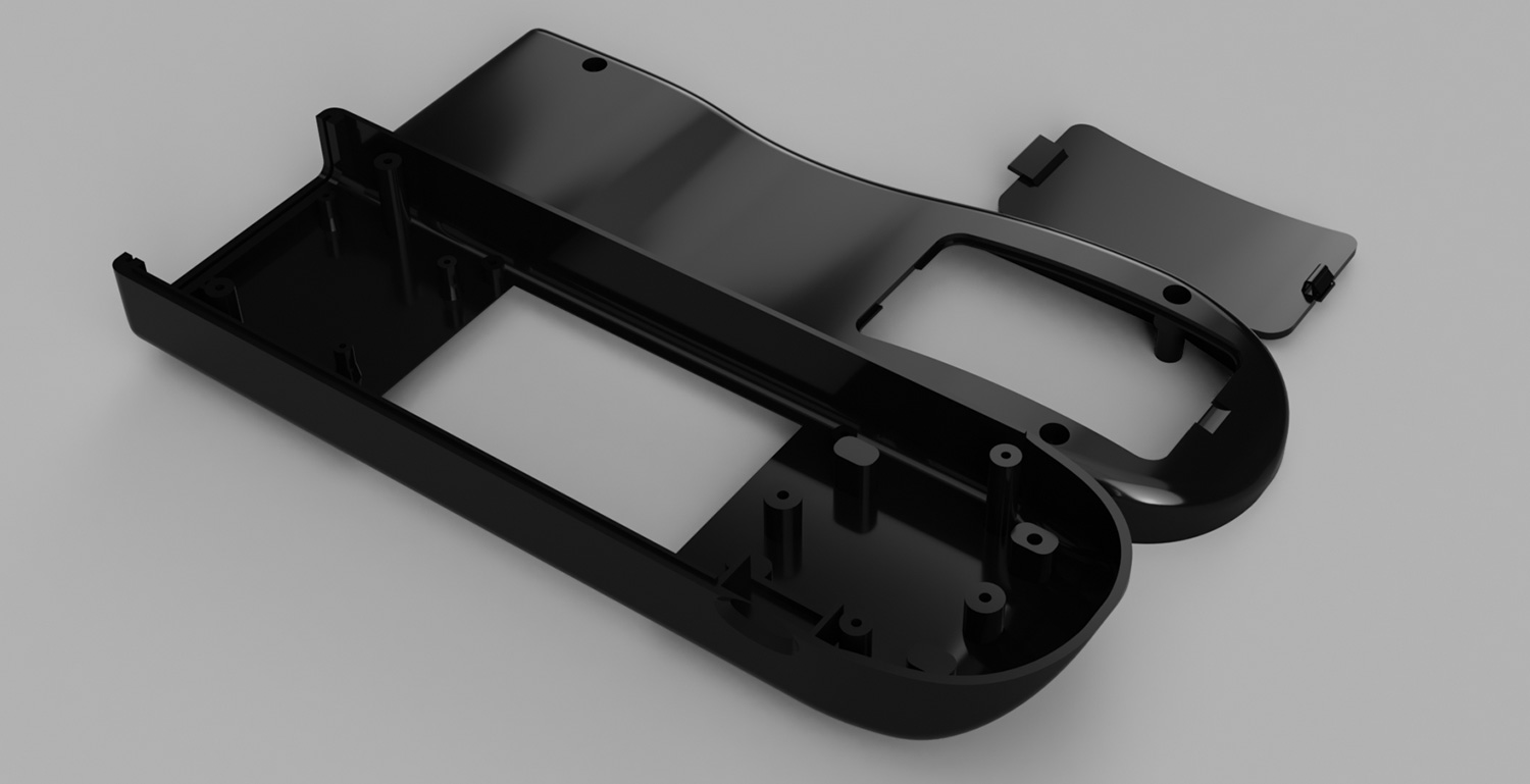
The exploded case was rendered using black ABS-style material.
The final case assembly with the red acrylic front panel for the laser scanner
The screen and circuits to go into the new case.
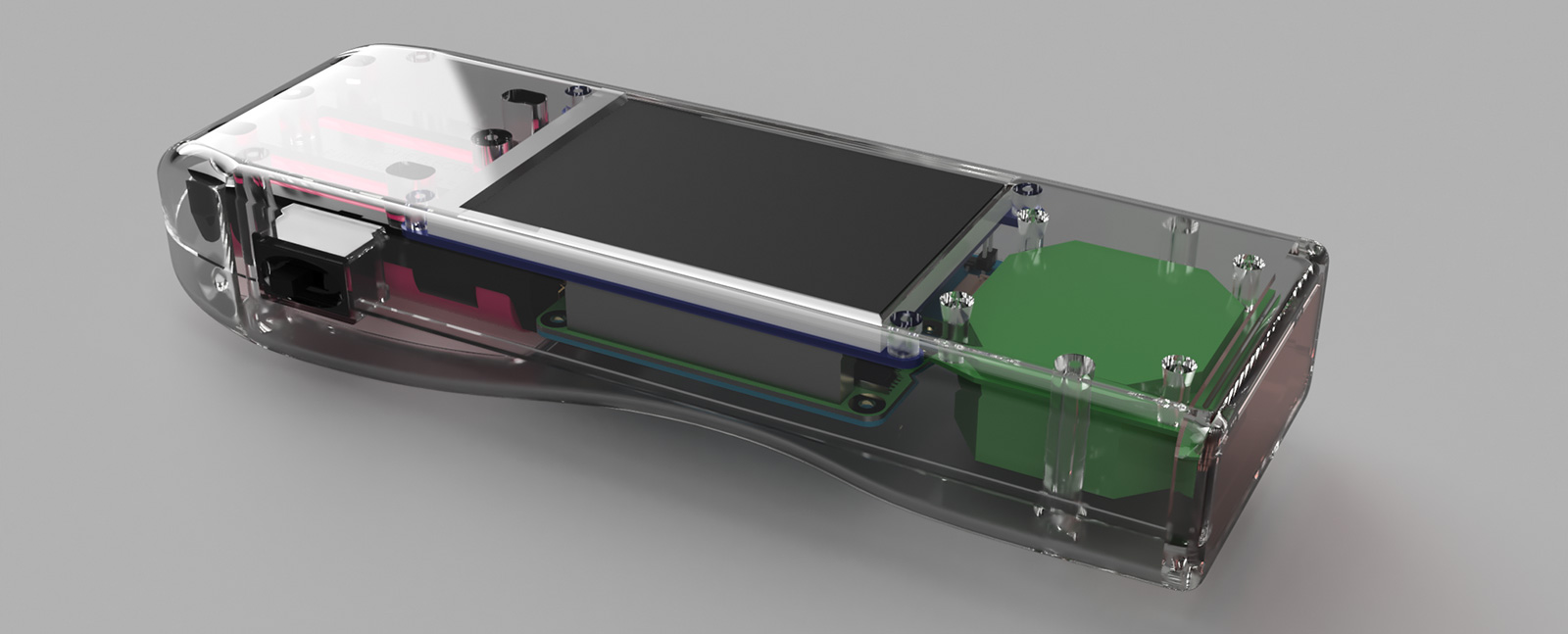
Final render of the case, battery holder, red screen, Adafruit TFT, Raspberry Pi and power board and laser scanner module (green box)
![]()
The 3d mesh was exported as an STL file and we ordered the parts from Shapeways. This is the first time we have used their service so it will be interesting to see how close the finished item resembles the CAD model. While we wait for the printed enclosure to arrive we will continue working on the software for the scanner.


Michael
where I can get from power board and the laser scanner module board
Brian
Michael, you can download the PCB files from https://github.com/briandorey/RaspberryPiBarcodeScanner
Michael M
1. list of components for power board its not there, or I missing something ?
2. laser scanner module come from Barcode Scanner ES015 ?
Brian
The Interface-Board.dip file is the power / interface board. The laser module came from the ES015 scanner
Michael
Thanks Brian
Diego Torres
Hello, I am very interested in this project and I just wondering when I send to print the PCB will come with all the components or do I have to soled and if so where is the list of all of the components that we need.
sorry guys Im kind of new on this...
Jørgen Skoglund Hansen
I would like to buy your finished product, where can i do so?
Michael Brenden
You guys should sell these. The units for sale on eBay for around $50 to $90 are garbage; one I tried killed the batteries within half-hour even when the unit was "off". LOL. The buttons are tiny; the interfaces are apparently made by people whose brains function wildly differently than normal humans. I would pay up to $250 any day for an open-source / all -design-files-available barcode scanner. Seriously, you should sell these; you're missing a gargantuan market.
mark
Is it possible to have the 3d model of the projet?
I need the 3d model of the lcd and scanner module
Brian
Mark, the download links are on the part 3 blog post https://www.briandorey.com/post/raspberry-pi-zero-handheld-barcode-scanner-part-3
Tanvir Shahid
Brian, are you selling the full package? I am interested to buy it.
Brian
I am sorry but I am not planning to make the scanner as an item to sell.