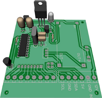
 To make it easier to connect the various cables to the new Raspberry Pi ADC board we decided to make a second PCB with header pins to connect to the ADC board and take these to screw terminals. Also, we wanted to have a temperature-controlled fan with variable speed control for the box so we built both onto the same PCB.
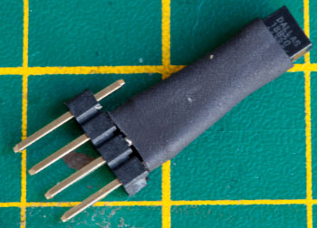
The speed controller uses a 1-Wire Dallas DS18B20 temperature sensor connected to a Microchip PIC 16 series processor which switches a variable voltage DC-DC converter via a Mosfet. This allows us to control the speed of the PC fan without generating a lot of excess heat which more basic voltage regulation chips seem to produce. The current consumption when running is around 30mA but with a normal fan speed controller, it was over 200mA. As the system is battery powered it was better to use the more efficient controller.
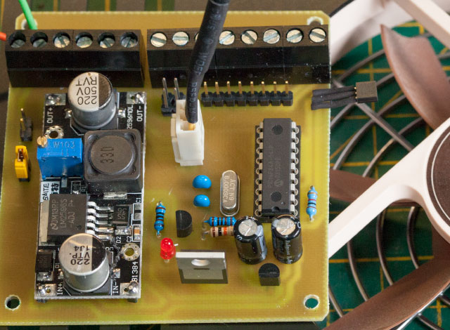
The photos below show the completed PCB connected to the fan with the temperature sensor on the right over the airflow.
Testing the board with the PC 120mm fan
The new board was installed next to the Raspberry Pi with the temperature sensor over the processor. Labels have been added to the board to make it easier to connect.
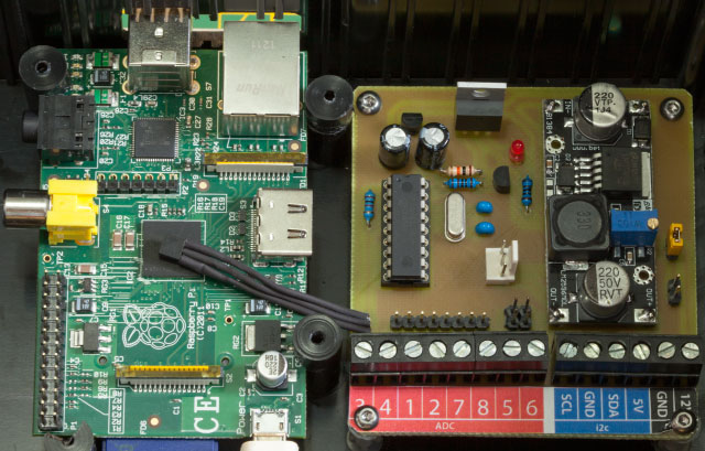
 The I2C connections on the Raspberry Pi do not seem to work with the longer cable runs which worked OK with the Arduino board.
To solve this problem we are using the 1-Wire Dallas DS18B20 temperature sensors on the solar collector and hot water tank as these seem more reliable over the greater distance but have the downside of being a lot slower to return data.
The initial Python functions are now working to retrieve data from the various sensors and the ADC board is working ok with the current and voltage sensors so next, we have to write the full script to collate the data and upload it to the server.
The PIC code and circuit layouts can be downloaded from https://github.com/briandorey/mikroC-Fan-Controller
Comments