
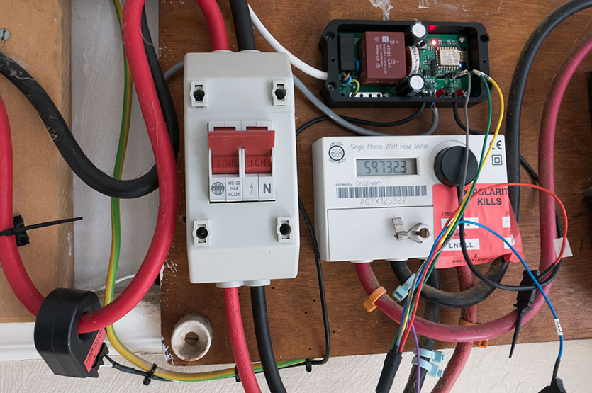
In a previous blog post, we wrote about our new mains energy monitoring system which reads the values from our electric and gas meters and stores them in an online database. The gas reading was done using a reed switch sensor which was supposed to be designed to work with our model of the gas meter. After the installation, everything looked like it was working properly but after a few days, we noticed that the gas reading on the energy monitor was lower than the dials on the gas meter.
After a bit of investigating we worked out that the reed switch sat right at the limits of the magnet inside the meter and was not triggering 100% of the time. As the reed switch was already as close to the gas meter as we could get it we decided to look at a different option for sensing the magnet.
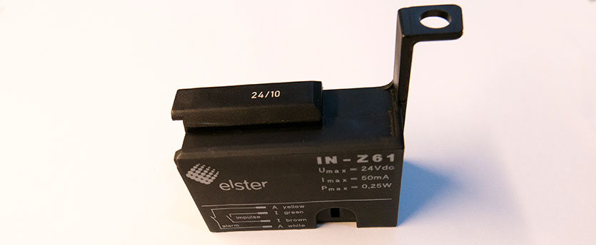
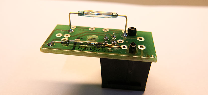
Original Gas Meter Sensor reed switches
The solution we came up with was to use a hall-effect sensor to measure the magnetic field and use that to trigger a timer when the magnet inside the meter passes over the sensor.
There are several different types of hall-effect sensors on the market, some of them act as a switch, triggering at a set level while others output an analogue voltage depending on the strength of the magnetic field. As we did not know what the strength of the magnetic field would be we decided to use an analogue sensor.
We chose an SS49E sensor from Honeywell as it would work at 3.3V which is the voltage the mains energy monitor runs at.
Breadboard Circuit Mockup
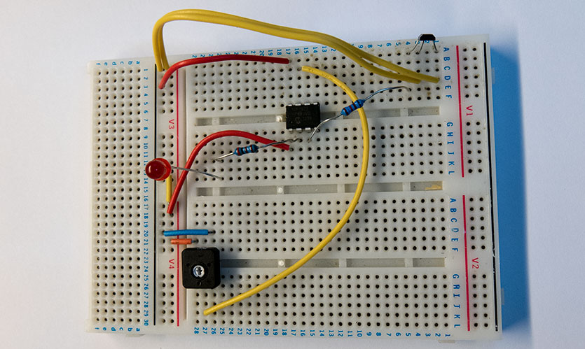
To measure the sensor and generate a pulse we used a PIC12F1822 microcontroller from Microchip. This is a small 8-pin microcontroller with an internal oscillator so it wouldn’t need many external components to build the circuit.
We wanted an easy way of setting the threshold for the hall-effect sensor once the circuit had been installed so we used the internal comparator on the PIC microcontroller with the sensor connected to one input and a potentiometer connected to the other input. That way we can set a threshold voltage on the potentiometer and use an interrupt that would be triggered when the voltage from the sensor exceeds the threshold.
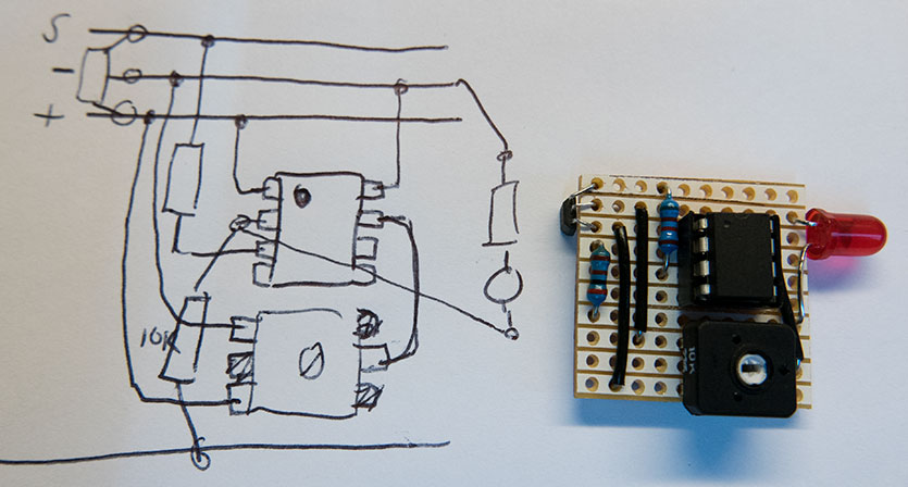
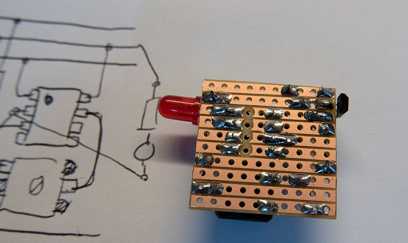
Circuit mockup and stripboard build with a sensor on left side
The software for the microcontroller is very simple. It waits for an interrupt on the comparator to trigger and then sets an output pin to be high.
The internal timer1 is then started which runs for 200ms before turning off the output pin and stopping the timer. This way when the magnet in the meter passes over the sensor a 200ms pulse is sent to the mains energy monitor which then updates the counter for the gas meter. We added an LED onto the output pin so we can see when the sensor is triggered.
Stripboard circuit base
The hall-effect sensor was fitted inside the original sensor box so it could be screwed up under the gas meter. Once we worked out exactly where the sensor needed to be placed inside the box we used some hot glue to hold it in place.
The circuit was very simple so instead of using the usual method of designing it in Diptrace and ordering a PCB we just sketched it out on a piece of paper and soldered the circuit onto a piece of stripboard. It doesn’t look as tidy as a proper PCB but it will be hidden inside a plastic box and tucked away inside a cupboard so nobody will see it.
So far we have had the new sensor running for several days and it appears to be counting all of the pulses.
Updating the firmware on the data logger.
The gas meter sensor firmware can be downloaded from my GitHub page: https://github.com/briandorey/ESP8266-Mains-Energy-Monitor


Comments