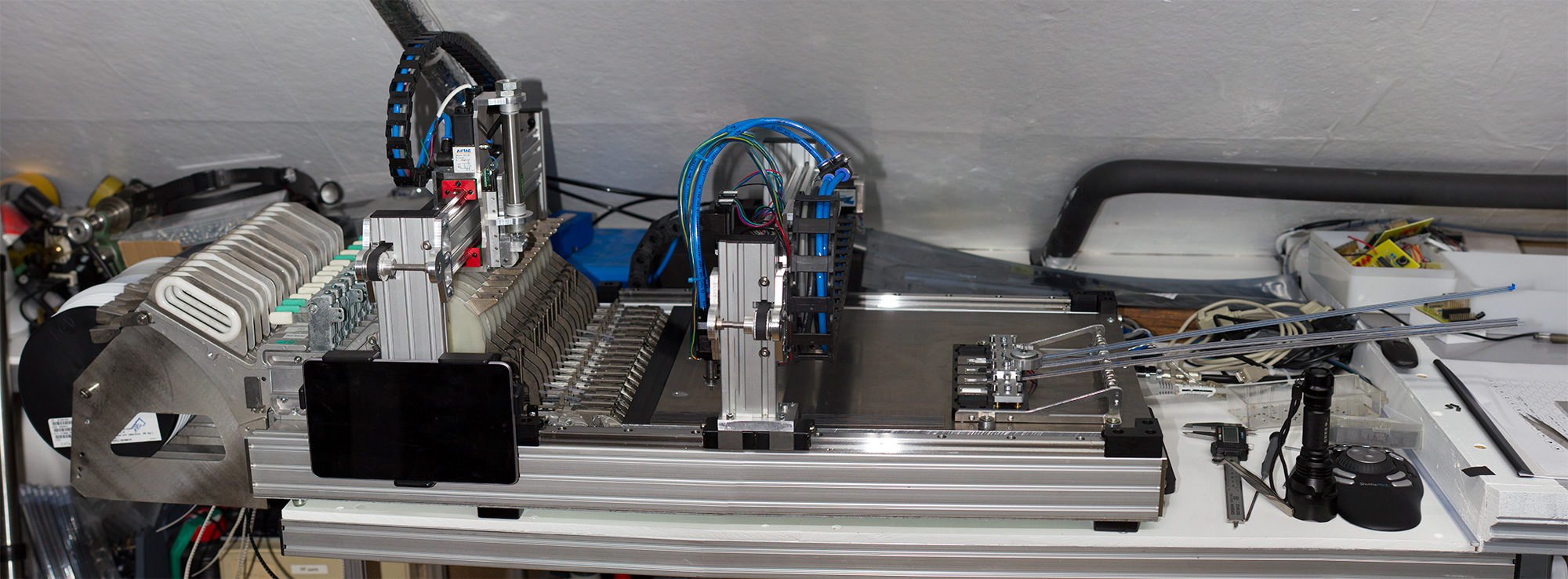
The DIY pick and place machine project is now finally running and is able to place the components for our Raspberry Pi expansion boards. This project started in July 2013 when we began to order the various components, bearings, motors, drive systems, frame materials etc and we started to build the machine in September.
Various stages of this project have been posted in the DIY Pick and Place category on the blog and this post will be an overview of all the stages during the build and the problems and issues we had to overcome.
This blog post is split into the following sections:
- Project Overview and aims
- Main Frame assembly
- Bearings and Drive systems
- Picker Heads and Vacuum Control
- Component tape feeders and actuators
- Tube fed chip feeder system
- Vision system
- Control boards and interfaces
- Software
- Project Videos
- Part Suppliers
- Future Plans and Upgrades
You can click on any of the photos to view larger versions.
Project Overview and aims
Early in 2013, we found that the manual pick and place machine we had built to place the surface mount components on our Raspberry Pi expansion boards was too slow to build the number of boards we needed to sell on our online store. We had been receiving a lot of requests from overseas distributors who wanted to stock our boards and we couldn’t keep up with the demand from our own customers without the extra quantities the overseas distributors wanted to buy on a regular basis.
We researched commercial new and used pick and place systems and found that they are very expensive and also very big and heavy and wouldn’t fit in our home workshop.
This left us with two choices: either borrow a lot of money from the bank and buy a commercial machine and rent or buy a business unit/workshop with all the associated costs or try to build our own pick and place machine which would fit in the space we have available and work with the modified commercial feeders we had previously purchased to use on our manual machine.
With the cost of the commercial systems with all the other kit being estimated at £50,000 + for the machinery plus annual costs of £10,000 + for rent/rates/power/heating etc, we decided to build our own pick and place machine.
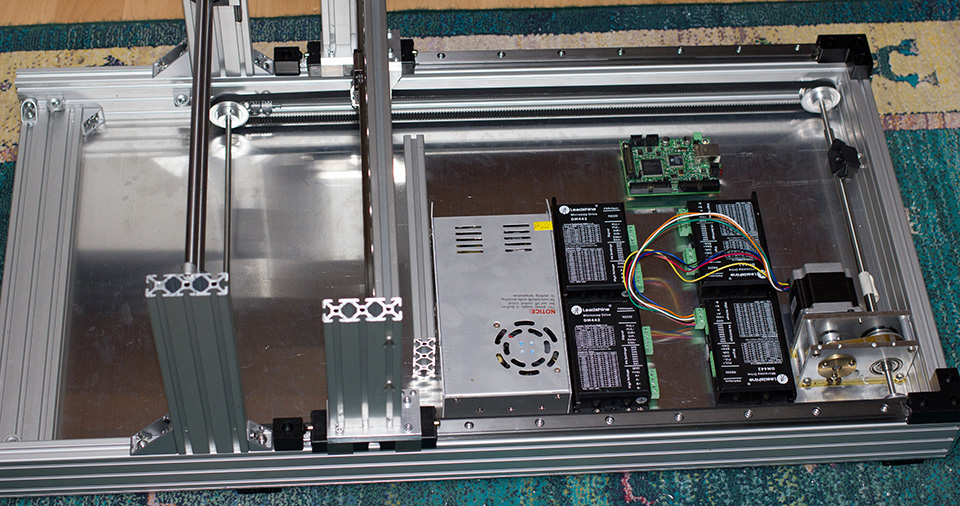
Main Frame assembly
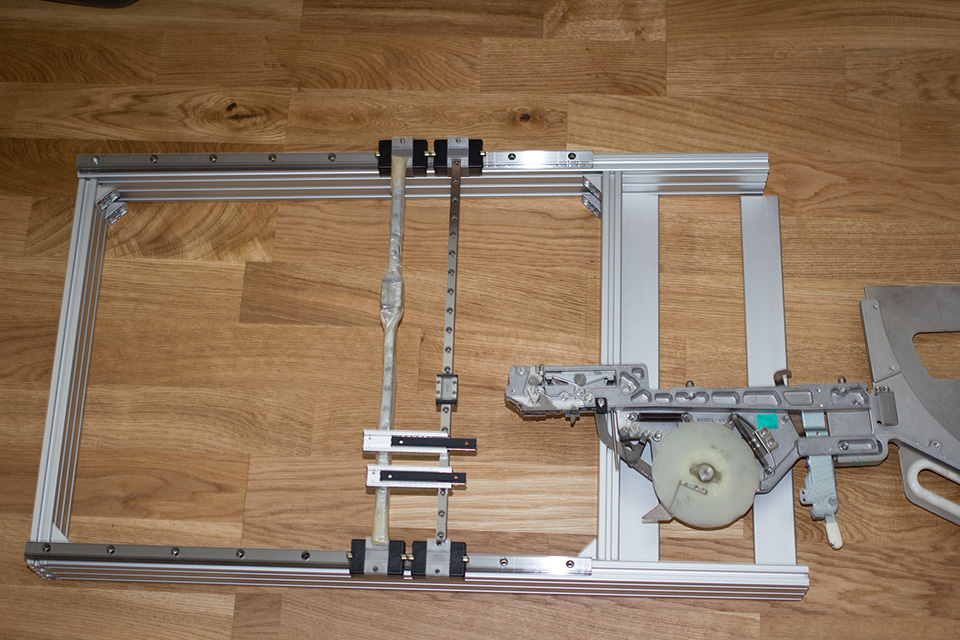
For the frame, we decided to try aluminium extrusion as this would be easy to assemble, light and ridged and allow us to easily adjust the positions of different parts by sliding them along the rails. The main framework is made using 60mm x 20mm extrusion with 20mm x 20mm used on the component picker rails and 40mm x 20mm used on the component feeder assembly.
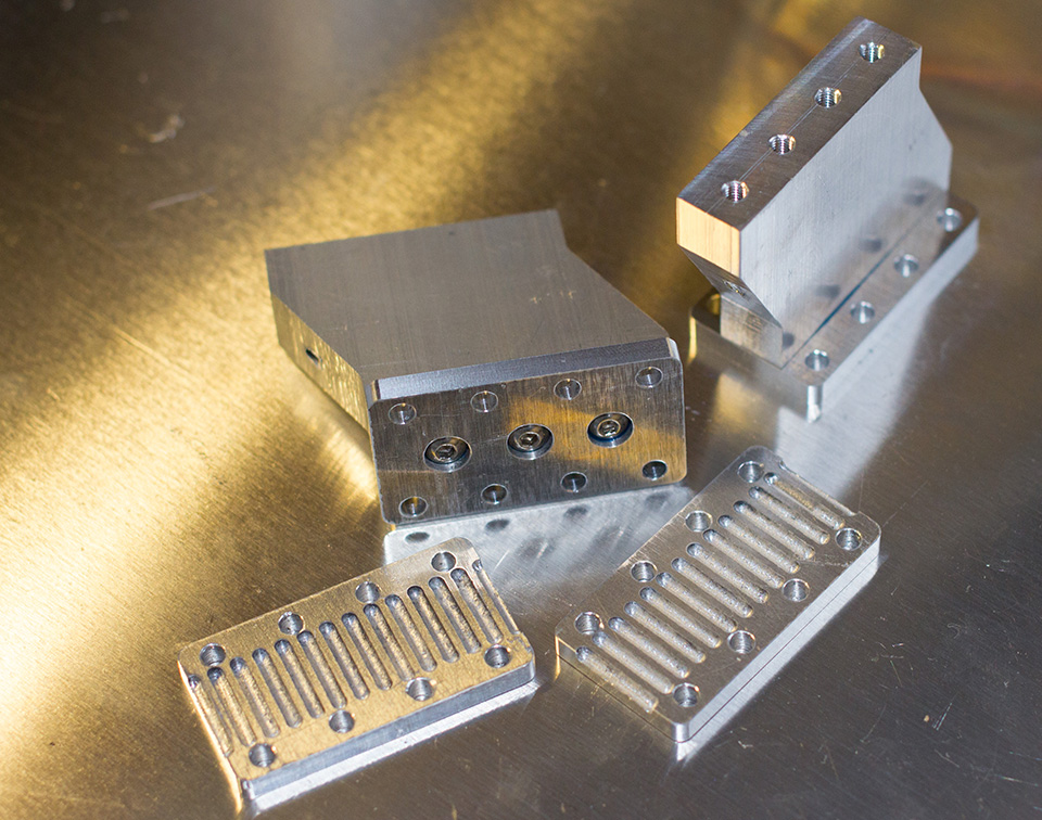
We machined various shaped plates to bolt all of the frame parts together.
The overall dimensions for the metal frame are 86cm long by 45cm wide.

Bearings and Drive systems
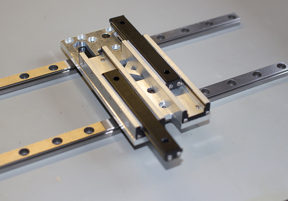
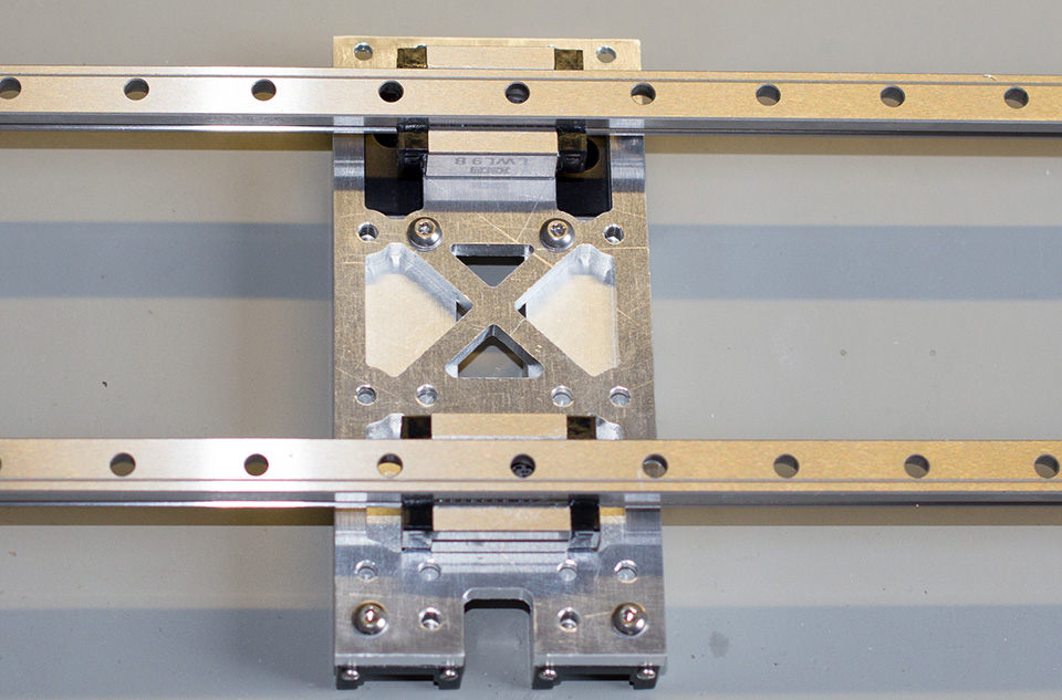
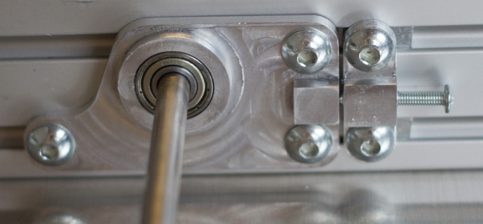
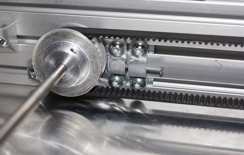
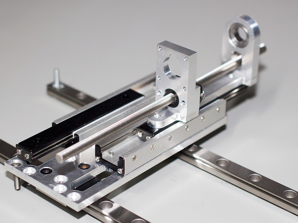
In our previous manual pick and place system, we opted to use cheap Chinese bearings from eBay. While these worked perfectly fine for manual placement the amount of sideways play in the bearings made them unsuitable for the accuracy we would need when placing on an automated system so we decided to use some good quality linear side bearings on the X and Y axis instead.
We used the same vertical slide bearings for the picker heads and component feeder heads as we used on the previous machine. These had the advantage that they were compact, precise and had built-in end stops so the heads wouldn’t accidentally fall off if we did something wrong in the software.
For the component feeder, we initially tried using some 10mm round shaft slide bearings which we had spare from a previous job but after designing a head assembly to fit on the bearings we found that the play in them was too great and it was causing the stepper motor to jam when we tried to run it quickly. We ended up using the same style of linear slide bearings as we have used elsewhere on the machine.

Picker Heads and Vacuum Control
We looked at various commercial and homemade picker heads before designing one to go on our machine. Some of the homemade pickers use belt drives for vertical movement, others use worm drives from CD-Roms.
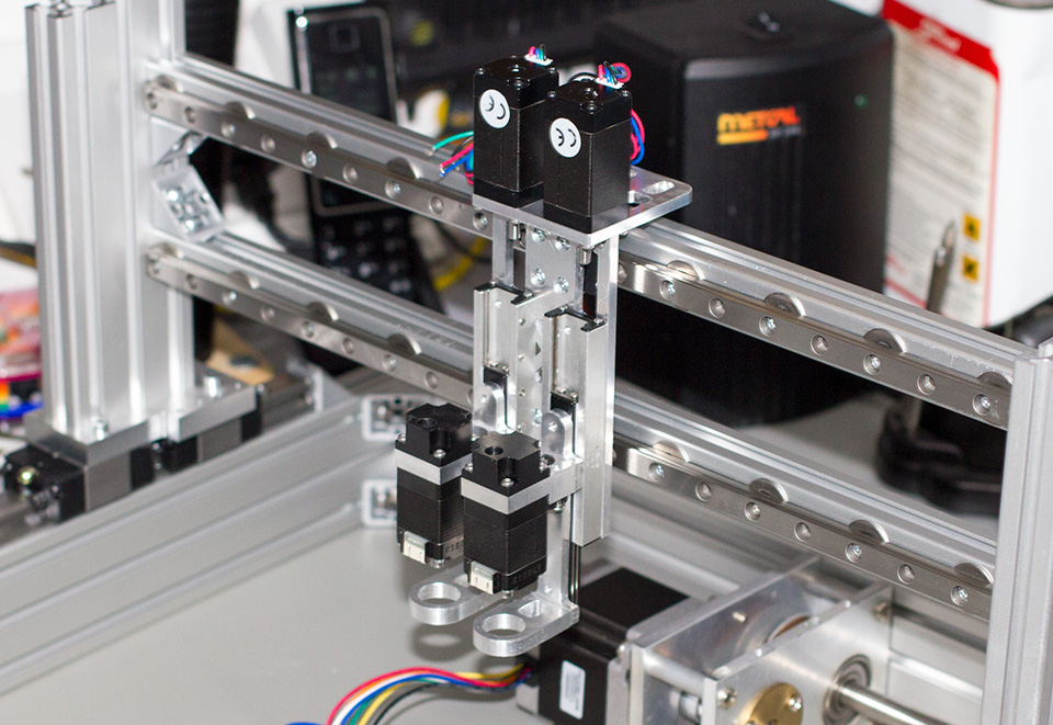
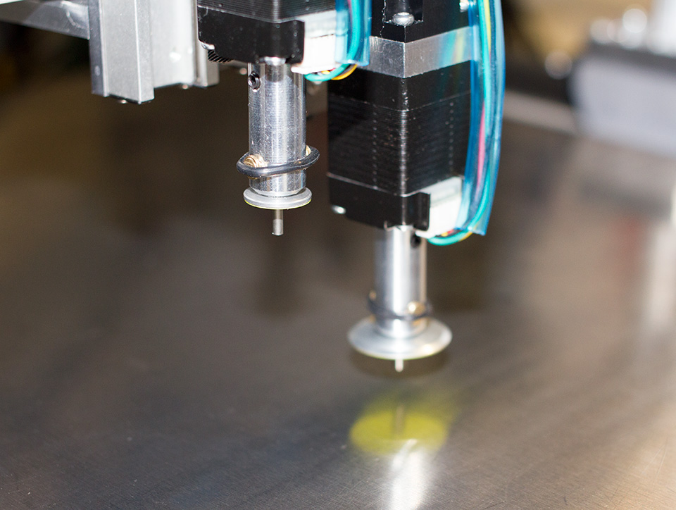
Our picker needed to be fast and precise so we decided on a high pitch lead screw with a Delrin nut connected directly to a Nema 8 stepper motor. We decided to have two picker assemblies as this would allow us to use two different nozzle sizes without having to change nozzles halfway through a build.
For rotating the components we decided that the easiest option would be to use a hollow shaft NEMA 8 motor with the nozzle fitted on one end and a Delrin cap fitted over the top end with the vacuum hose attached. This would allow free rotation of the nozzle without leaking air into the vacuum hose.
We decided to use commercial nozzles as the lathe we own isn’t accurate enough to make several different sizes to exactly the same length and tolerance. A coupling system was designed using a pair of brass pins held onto the motor shaft with a rubber O-ring. This allows us to quickly pull out a nozzle and replace it with a different size. It also adds a small amount of spring into the nozzle assembly so if it pushes down too far with a component it will not damage the component or lose track of the picker height.
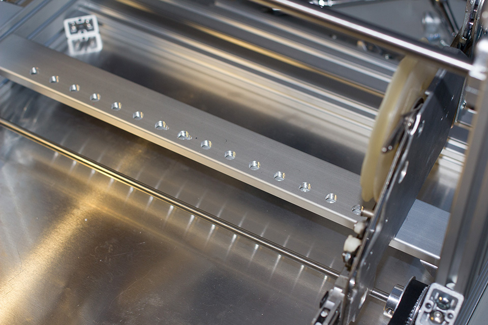
Component tape feeders and actuators
When we designed the manual pick and place machine we tried several different methods of feeding the components from their paper reels. We initially went with a simple block of metal with grooves cut into it so the paper could be pulled forwards and the components lifted out with a vacuum pickup. This worked ok but you had to pull the cover off of the tape by hand which had a nasty habit of causing the paper to spring upwards throwing components everywhere. Next, we tried making a way of automatically feeding the paper reels but we couldn’t come up with a design that would feed them exactly the right distance every time while pulling the plastic tape off by just the right amount.
While looking around on eBay one day we found someone selling used commercial Panasonic feeders for 8mm reels which is the size we use most. They were selling for £20 each which is a lot cheaper than they are new and they had quite a few in stock. We initially bought two feeders to see if they would do what we needed. We had to make a few modifications to make them work on our manual pick and place machine but they turned out to be reliable and easy to use so we went back to the seller and bought another 20 feeders.
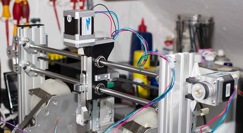
On our manual machine, we designed a gantry system for the component feeder which consisted of a pair of stepper motors and a vertical slide. One of the steppers would move the slider across to be above the required component feeder and the second would use a lead screw to push the slide down onto the component feeder activating it and feeding a component forward. As this system worked well on the manual machine we decided to copy it for the new machine.
We ended up going through three different designs for the feeder mechanism on the automatic machine. The first version was a slimmed-down design based on the feeder from our old machine. We use a pair of round rails with slide bearings housed in a Delrin block with the vertical motor and slide fitted on the front. This looked like it would work well enough but when we tried driving the stepper motor quickly we found that the bearings had too much play and would jam causing the stepper motor to lose steps and throwing everything out of alignment.
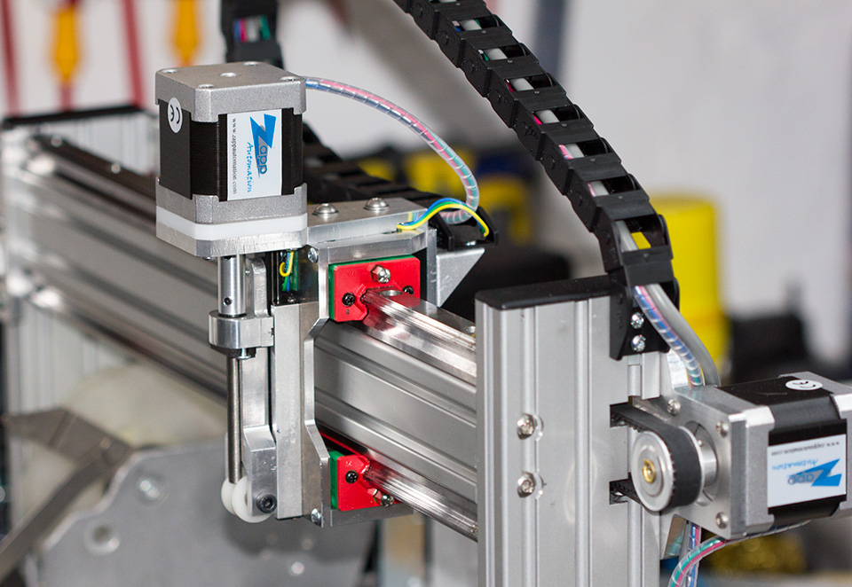
The second version used linear bearings similar to the ones we used on the main slides. This had far less play than the cheap Chinese bearings we previously used allowing us to drive the motor faster and more accurately. This version of the feeder system worked well for the first few hours of use but then we found that the motor on the vertical slide would start to jam and skip steps. It turned out to be a combination of the stepper motor not having enough torque to drive the lead screw properly and the Delrin nut on the lead screw wasn’t up to the task of taking the load we were putting onto it.
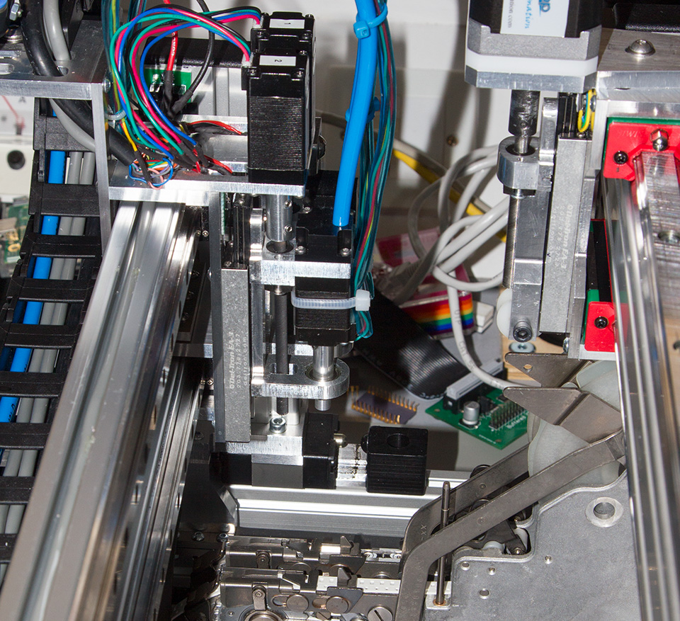
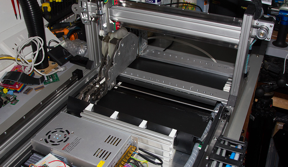
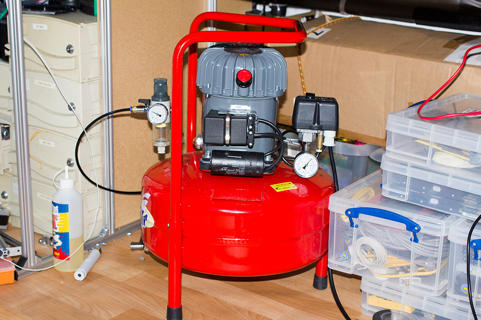
For the third version of the component feeder, we decided to scrap the stepper motor on the vertical slide and replace it with a pneumatic ram which is activated by a solenoid on the head assembly. We had to buy a silent compressor as the cheaper workshop compressors are very noisy and would have annoyed the neighbours but this new design appears to be working well and can pick components far quicker than any of our previous designs.
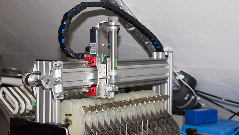

Tube fed chip feeder system
The feeder system for tube-supplied chips is a vibration feeder which shakes the chips down the tubes and into a picker location at the base.
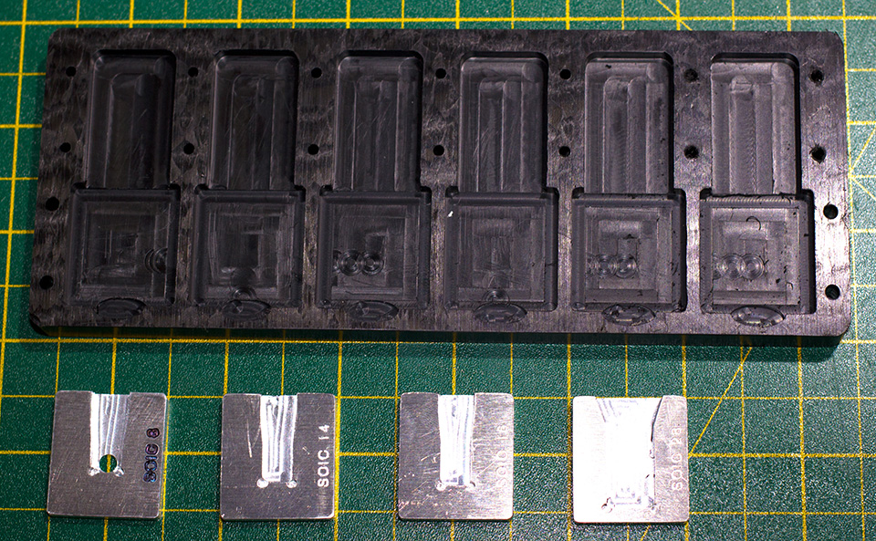
The base of the assembly was machined from a section of 20mm Delrin sheet and the separate inserts for each chip size were from 4mm aluminium sheet. Over this, a clamping plate was fitted and this holds a vibration motor from an Xbox game controller. At the rear of the feeder is a threaded bar which uses nuts to clamp each side of the component tubes.
The motor is controlled via the PC software and runs for approx. 750ms each time to feed a new chip into the base ready to be picked and placed.

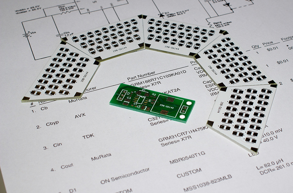
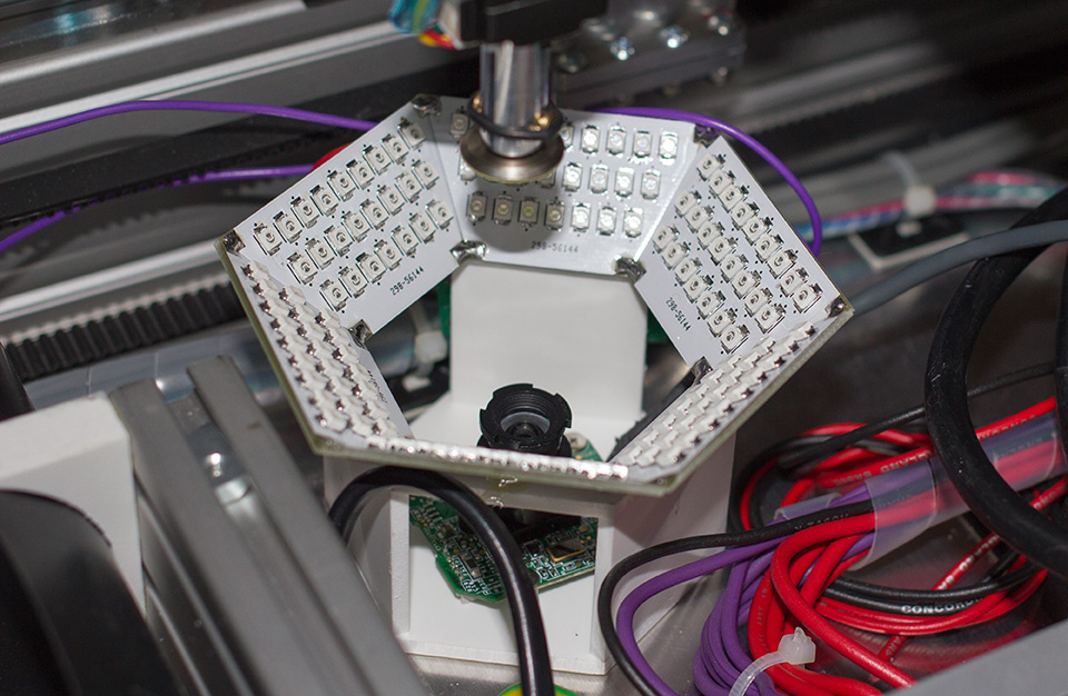
Vision system
The vision system compromises of two USB cameras, a base camera with a large LED array which will use OpenCV to detect the component held above and determine if the position and rotation are correct and apply any changes necessary and the head camera will be used to find the location of the PCB and set the offsets. It will also be used for manual placement.
The base LED array has 140 red LEDs controlled via a custom driver and dimmer board.
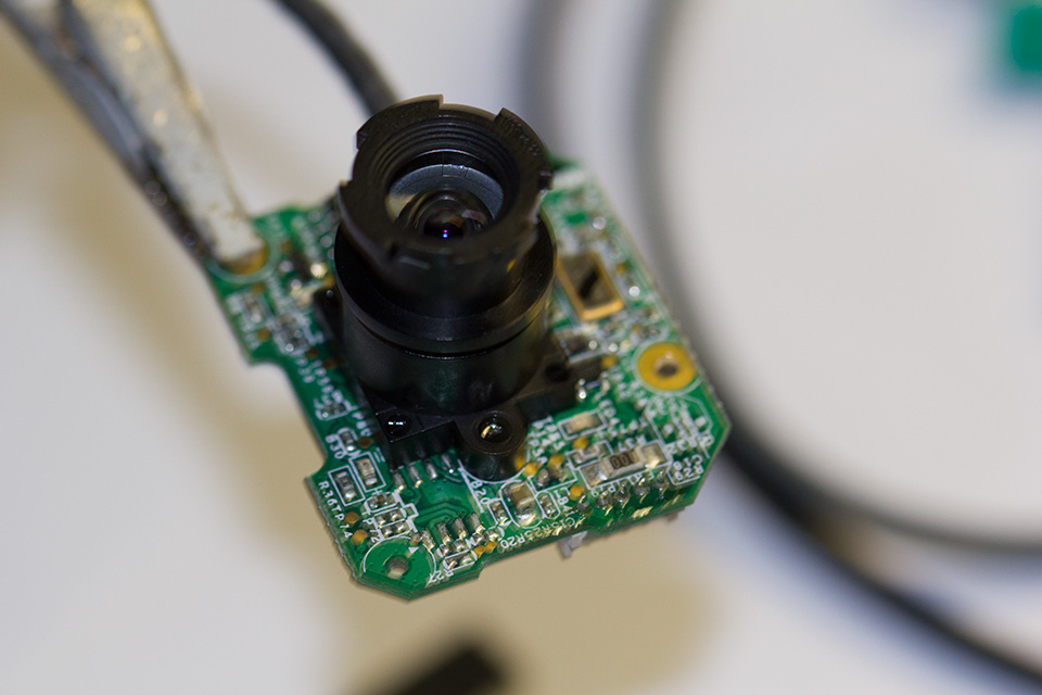
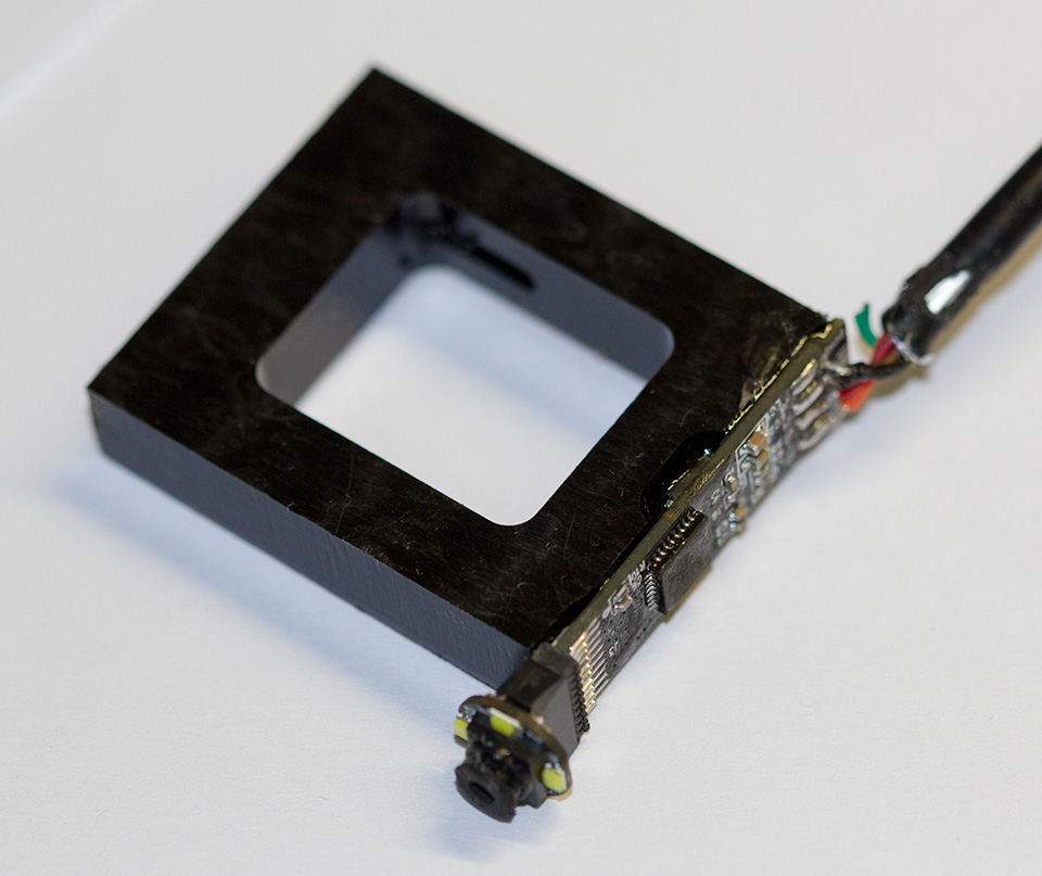
The base camera module is from a Microsoft Xbox vision camera and the small head camera which is 8mm wide is from a Hong Kong eBay seller and was sold as an endoscope camera with a 10m lead.
Control boards and interfaces
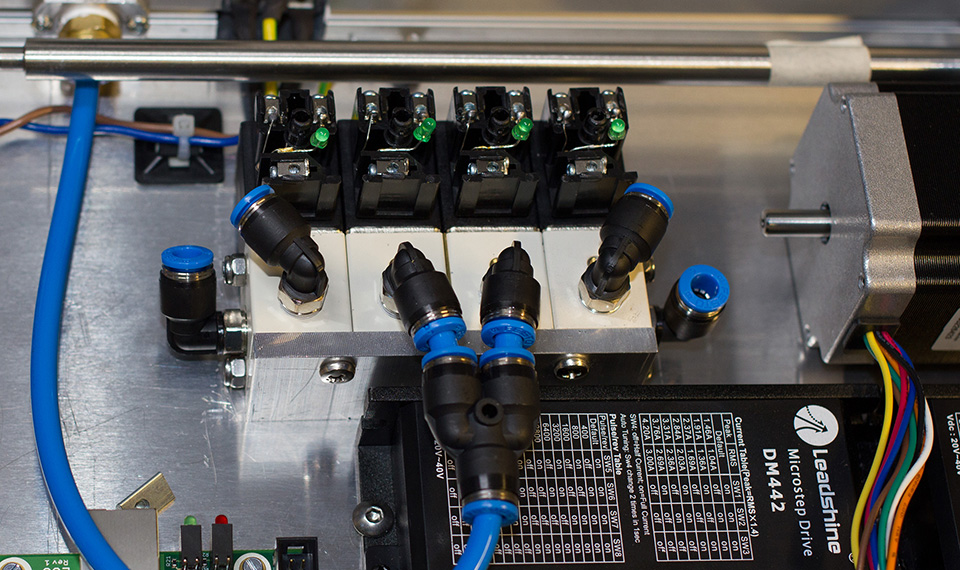
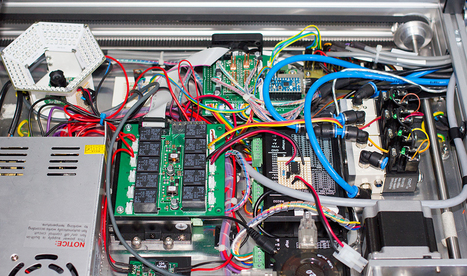
For controlling the pick and place machine we decided to use a combination of commercial drivers combined with parts which we designed ourselves.
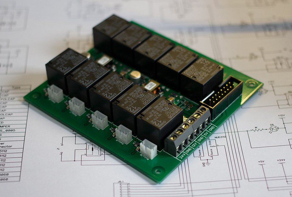
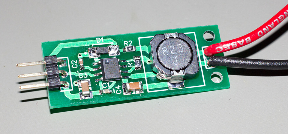
Power is provided through a 15 amp 24V switch mode supply. The NEMA 17 and NEMA 21 motors are driven with commercial stepper drivers which run at 24V while the NEMA 8 motors on the picker head are driven using Pololu A4988 drivers running at 12V. All of the logic circuits run at 5V so we designed a power supply and relay control board which used a pair of PTN78060 DC-DC converters from Texas Instruments to drop the 24V down to 12V and 5V.
For controlling all of the motors and relays we went with a Smoothstepper Ethernet controller. To interface the Smoothstepper with the rest of the machine we designed a breakout board that connected directly to the top of the Smoothstepper. The breakout board contains connectors for all of the stepper motors and end stop sensors as well as four Pololu drivers and an Arduino Mini.
The Arduino is used to control the feeder assembly. When a new component is needed 5 pins on the Smoothstepper are set to be either high or low giving a binary number for the required feeder. A 6th pin is then put high which activates an interrupt on the Arduino. When the interrupt is triggered the Arduino reads the 5 pins to get a feeder address and then drives the stepper motor to move the head to be above the correct feeder before turning on the pneumatic solenoid which pushes the ram down onto the feeder. When a new component is selected the Arduino turns off the solenoid and waits for the ram to lift up high enough to activate an optical switch on the head. Once the optical switch is activated it knows that the feeder's head is clear of the feeders and it can then move across to the next component and repeat the process.
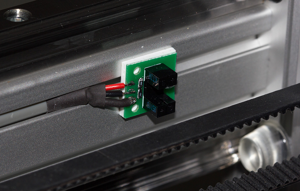
A small PCB was designed for all of the optical stop switches needed on the machine. We designed the PCB so it could be used with slotted or reflective optical switches depending on where they were being used.
For driving the LEDs we designed a constant current driver based on the LM3404 from Texas Instruments. The drivers can be dimmed using a logic-level PWM signal from a microcontroller.
A ribbon cable joins the breakout board with another board containing the power supplies and relays for activating various parts of the machine. The ribbon cable provides power to the smoothstepper board and communication between the smoothstepper and the relays.

Software
We had originally planned to use OpenPNP with the pick and place machine with Linux CNC but we had a lot of problems with Linux CNC recognising the PCI express parallel port cards we had purchased and this also did not have enough ports for all the stepper drivers and sensors we had planned to use.
After a lot of research, we decided to go with a SmoothStepper Ethernet board from Warp9 Tech Design which had a lot more IO ports and would work with our existing Mach3 mill software and we could control the system using GCode and the Mach3 API. The SmoothStepper Ethernet also only needed a Cat5 Ethernet cable to connect to the host PC.
We started by writing a series of Mach3 macros to control the valves, relays and interface with the Arduino board to control the component feeders but we found that the macro system in Mach3 is very slow and adds pauses up to 1 second on each macro request which was causing long delays with picking and placing components.
I found a blog post which showed how to connect to Mach3 and send commands directly into the application via an API using Visual Studio. I started with a basic application which would send the GCode commands to trigger the outputs for the relays and Arduino directly which we found had much shorter delays.
I then proceeded to start working on a more fully featured Windows application to control the pick and place machine and include camera vision using OpenCV. This first application loaded CSV board files which contained the component's location, rotation and type which loaded into a grid view control, then the application looped over each row and selected the required feeder and then placed the component.
We then found that some PCB boards would need a slightly different offset depending on the board layout and if it was a PCB panel with several boards on each main PCB.
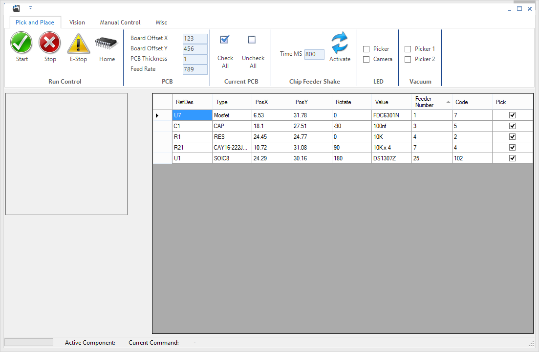 I started working on a new version 2 application which is loading the board’s component list and also board settings including offsets, feed rates and board thickness which is used to calculate the correct placement height.
At the present time, the basic functionality to build boards is working and I still have the vision system and manual control system to complete to interface it with a Leap motion controller.
The source code for the app is on GitHub at https://github.com/briandorey/pickandplacesoftware.
Project Videos
Below are videos we have filmed during the build process:
Part Suppliers
Bearings: Hepcomotion www.hepcomotion.com, Ebay and Moore International Ltd www.mooreinternational.co.uk
Stepper Motors and Drivers: Zapp Automation Ltd and Protopic proto-pic.co.uk
Belts and Pulleys: Motionco www.motionco.co.uk
Aluminium profile extrusion: Metallin (no longer trading)
Other frame materials: Aluminium Warehouse www.aluminiumwarehouse.co.uk and Forward Metals www.forwardmetals.co.uk
Smoothstepper Ethernet: Warp9 www.warp9td.com
Lead screws: Reliance Precision Mechatronics www.rpmechatronics.co.uk
Picker nozzles: Surface Mount Engineering www.surfacemountengineering.com
Pneumatic system: Airlines Pneumatics www.airlines-pneumatics.co.uk
All other parts were sourced from eBay.
The total cost of materials and parts to build this machine was £3659.60
Future Plans and Upgrades
 After using the machine for a few days we have found a few small but annoying limitations with the Mach3 and SmoothStepper interface. When a command is sent to turn on or off one of the relays or send the commands to actuate the feeder system there is a short delay of between 100ms and 200ms and the movement of the main stepper drivers is halted during this delay. Over the course of building some of the larger boards which have up to 150 components, this adds up to a long delay during the build process.
To resolve this we are looking into building a custom USB-based interface board using a PIC microprocessor which will replace the current relay board, Arduino Mini for the feeder X-axis drive and the control of the control valves and head and base LED drivers and dimming. This will combine all the current external PCBs into a single board and save a lot of extra wires and interconnections. We will use MOSFETs to switch the control valves rather than relays which will also slightly increase the response time to activate and deactivate. The board will also include a built-in USB hub so the USB cameras can all connect to the single board and have one cable going back to the PC.
This will keep Mach3 and the SmoothStepper board free to just drive the main steppers and only have the home/limit switches still interfaced on this board.
The revised control application will then be able to issue commands under different threads to Mach3 and via USB so it won't have to wait for one command to complete and pause everything else while it is processing.
We are also planning to add a manual placement mode which will be controlled via a Leap Motion Controller to move the main X and Y axis drives and tablet control to select the required component which will then pick up the component and return to the previous location to place with the position being supplied by the centre point of the head camera.
Dude
Parts list would be nice
Maxim
part list would be nice, install KIT will be MAGIC !!!
Arkadiusz
Machine looks amazing great job! I'm in the process of building pnp machine myself.
Can you tell me where did you source LED panels for up looking camera?
Thanks
Arkadiusz
Brian
Arkadiusz, we designed the LED panels, https://www.briandorey.com/post/diy-pick-and-place-v2-base-vision-led-array
Melitonas
Hey, great project! How do you use the compressor as a vacuum? I am searching for silent vacuum solution for my DIY Pick and Place machine and found your blog post with this silent compressor. Very interested in your results!
Brian
Melitonas, we have a vacuum pump to generate the vacuum for the pickers
Fariborz
Very good
tanvir mahmud
what type of firmware you will use for this project.
Joseph Mella
This is really informative.
Interesting IC Feeder and Pick / Place.
Thank you for sharing.