
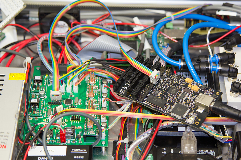
After completing our DIY Pick and Place machine we soon found a limitation with the SmoothStepper Ethernet board when using it to switch the various relays and select components from the Arduino Mini-controlled component picker system.
Every time the Mach3 software sent a command there would be a short delay of around 100-200 milliseconds and with each component placed using around seven commands, it was adding a few seconds to the placement time for each part. On some of our boards which have over 100 components, this was adding a sizeable delay to each board build time.
To resolve this and also to reduce the number of separate boards in the machine we decided to build a single controller board which would have its own microprocessor and switching systems.
The original system had the following circuits/controllers:
- SmoothStepper Ethernet interface driven via Mach3 on the host PC.
- SmoothStepper daughter board with an Arduino Mini to drive the X-axis stepper motor on the picker system and inputs for the limit switches.
- The relay and PSU board connected to the SmoothStepper daughter board via a ribbon cable, this had the 12v and 5v power modules and relays which switched the LEDs and the various solenoids on the machine.
- Led driver board for the base camera-led system.
- Led driver board for the head led
- LED PWM board for the base camera led for dimming the output.
- LED PWM board for the head led for dimming the output.
- PWM driver for the vibration motor.
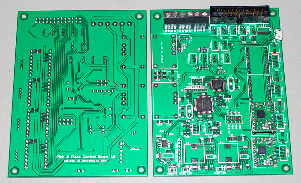
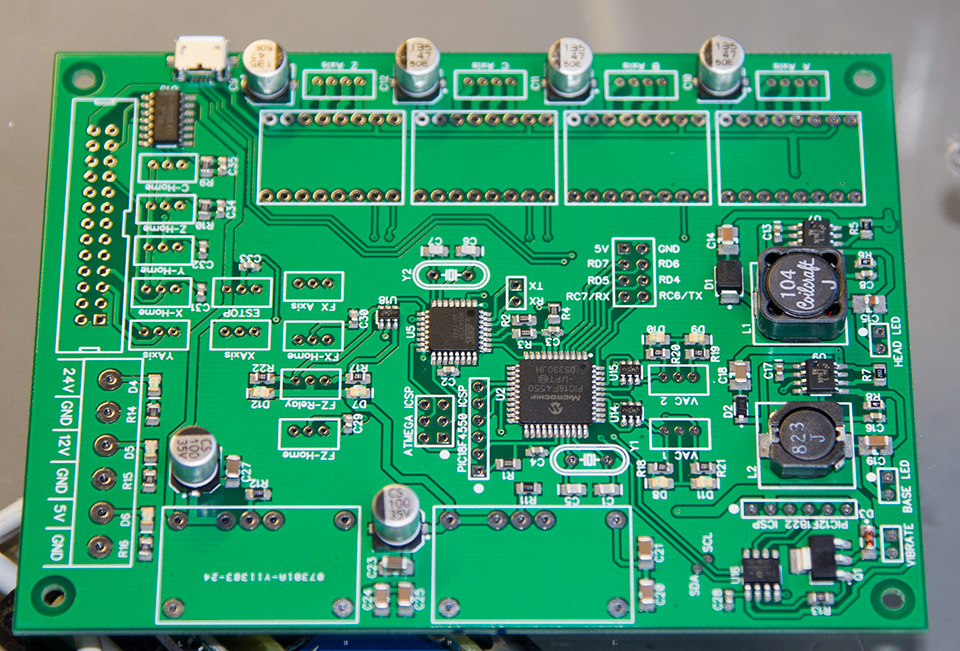
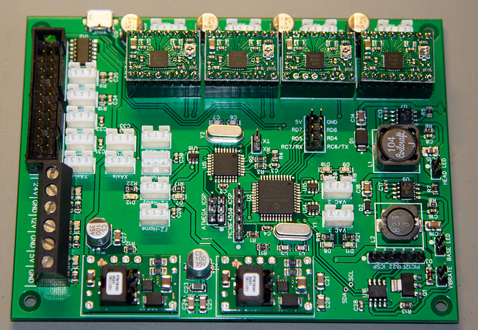


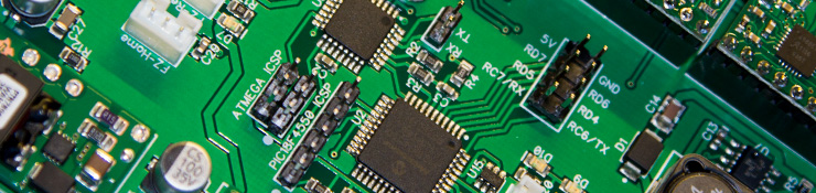
The new controller board combined all the drivers and other controllers onto a single PCB which is controlled via USB, appearing on the PC as a USB HID device. The main Microchip Pic is a PIC18F4550 with a USB interface, the PWM vibration motor controller is a PIC12F1822 and an Atmel ATMEGA328P was used as a stepper motor controller. The three chips communicate via I2C and the PIC18F4550 sends the commands to the slave chips based on the USB commands sent via the host PC.
We choose to use several different microcontrollers for a few reasons. We are more familiar with the Microchip PIC controllers so these were our first choice for the main processor. After choosing a PIC for the USB host we found that it didn’t have enough PWM outputs to control both LED arrays and the vibration motor output so we delegated the vibration motor to a separate 8-pin PIC. We choose an Atmel chip for the stepper controller because we wanted to use the same code as on the previous version of the control board and delegating the stepper driver to a separate microcontroller would allow it to generate the pulses for the stepper motor without pausing every time a USB command came in from the PC.
After building the control board we initially had problems getting Windows to detect it as an HID device. After a bit of head scratching and trawling through the datasheet for the PIC processor we found that we had forgotten to add a 220nF capacitor between the Vusb pin and ground so the microcontroller was not generating the correct voltages on the USB data lines. This was solved by soldering a capacitor between the two pins over the top of the microcontroller. Not the prettiest of bodges but it works.
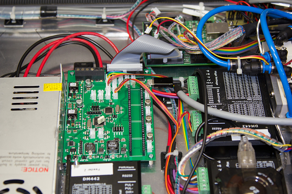
Our previous pick and place software was then updated to issue USB commands rather than via the SmoothStepper board and after a few small issues such as the wrong valve switching we were able to run some test board files on the machine which are a lot faster than the old system.
The circuit schematic can be downloaded in PDF format.
The video below is an overview of the new board and a preview of the machine running a board build file.
The code for this board can be downloaded from https://github.com/briandorey/PNPControllerUSB


Comments