We needed to be able to test some of our circuits for EMI issues via the power lines and after some research, we found a product called TBOH01 5UH Line Impedance Stabilisation Network LISN from Tek box.
The 5uH LISN from Tekbox has been released under an open hardware license and they have released the Gerber files for the PCB and also full schematics and build instructions. They sell the Tekbox TBOH01 for around $250 (£270 in the UK).
There is a post on the EEVBlog forum http://www.eevblog.com/forum/projects/5uh-lisn-for-spectrum-analyzer-emcemi-work/ which has a lot of examples of similar builds using the same circuit.
We ordered the parts needed to build the project and the cost including the PCB was under £50.
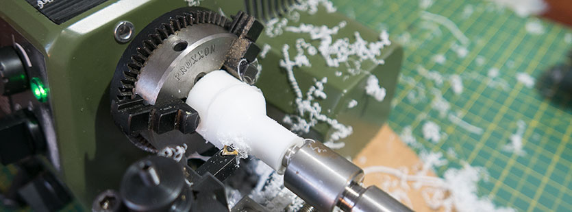
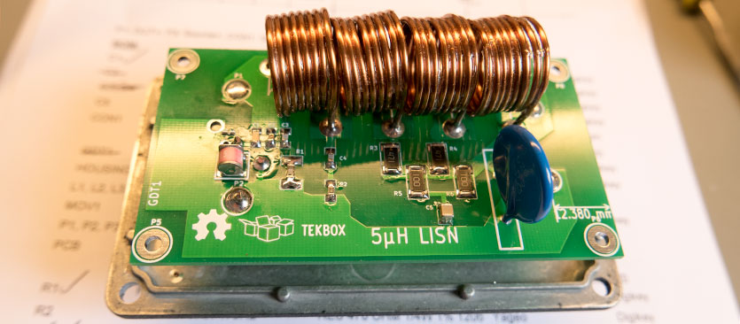
The LISN needed inductors to be hand wound and these needed to be 17mm in diameter. We machined a plastic former on the lathe and wound the coils using 1.4mm enamelled copper wire from http://www.wires.co.uk/
To stop the coil turns from moving we dipped them in varnish and left them to dry clamped in a vice.
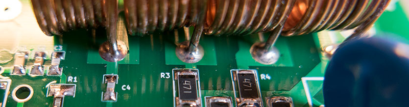
Once the varnish was dry we scraped the enamel from the ends of the inductor coils and soldered them to the PCB.
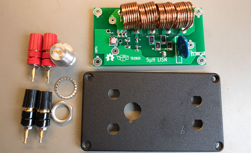
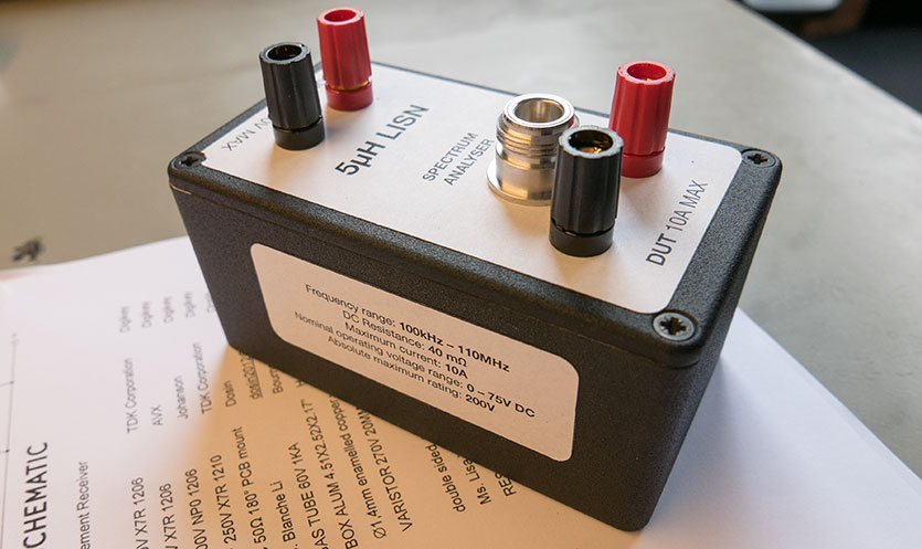
For the case, we decided to fit all the connectors into the lid of the box and the ends of the banana sockets are soldered directly to the pads on the base of the PCB.
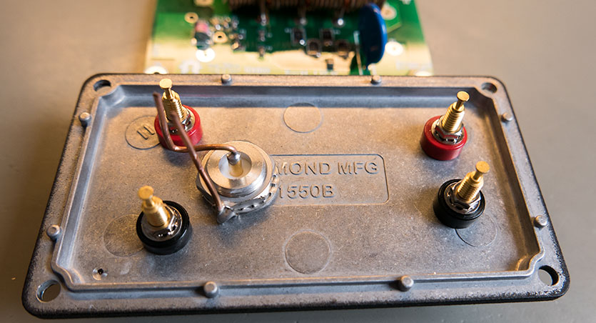
This securely mounted the PCB to the case and meant that we didn’t need to use flexible wires to connect between the sockets and the PCB.
We cleaned the paint from the edges of the box to ensure a good electrical connection between the lid and base.
Once the LISN was assembled we tested it using a nixie tube clock project which Andrew has been working on. The clock has switching power supplies and we expected it to generate some low-level interference on the power lines.
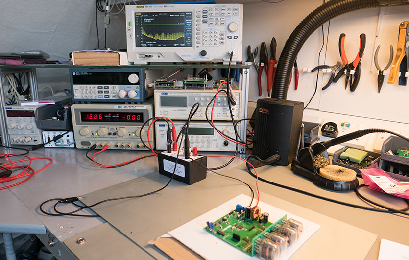
With the LISN connected to our GW dual-tracking power supply.
Test results
The screenshot below shows the baseline reading from the Rigol spectrum analyzer
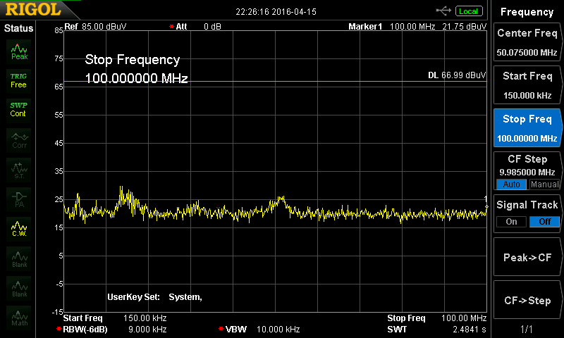
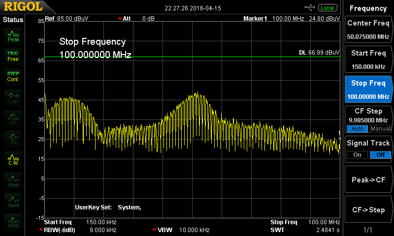
With the power turned on and connected to the clock we observed the following EMI being returned along the power lines.
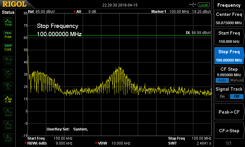
We then fitted a ferrite core to the positive wire with a single turn around the core which reduced the EMI
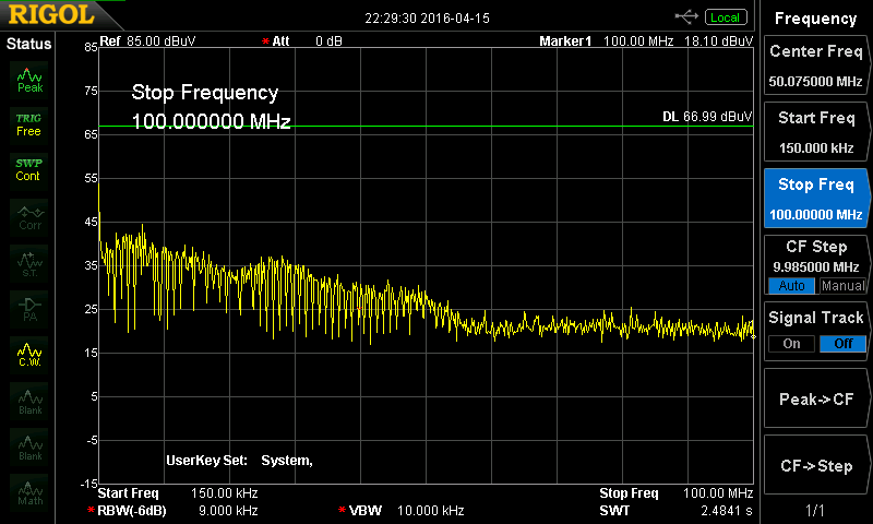
Next, we fitted a ferrite core to the negative line which reduced this further.
sismayo
Do you want to sell the PCB and coils ?